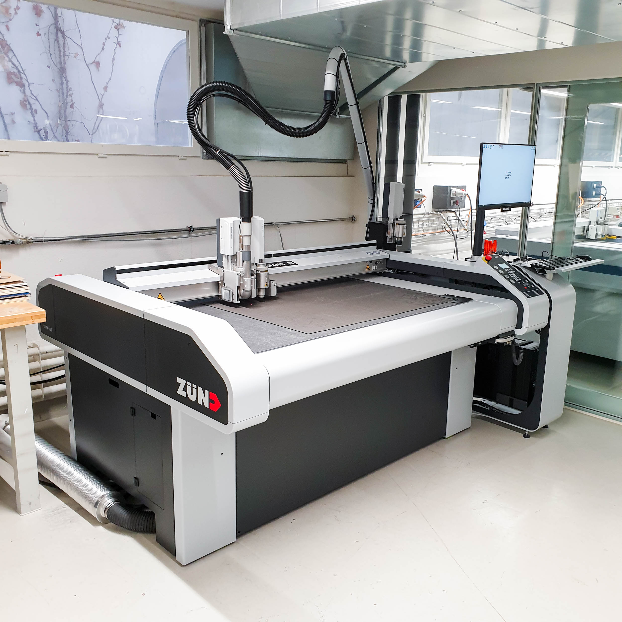
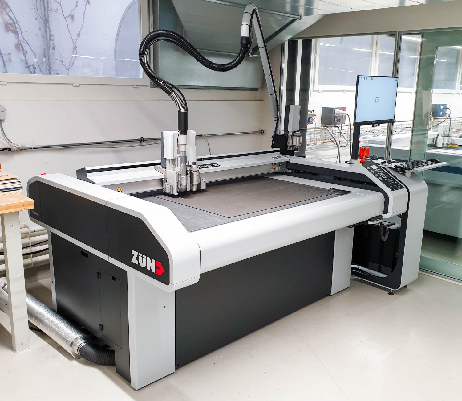
Open the cut editor located on the desktop. Click import and select your file
Import settings
Check the option to rotate -90°. If you have a cut layer ensure the bridges box is checked.
Move job
The corner of your stock rectangle should be lined up with the bottom right corner. If you need to move or rotate your job: select all, right click and choose numerical geometry.
Material settings
Click the pencil next to material in the top right corner to open the material settings. Ensure MDF is selected and input the length, width and thickness of your material. The light blue area on screen should match your stock material.
In the next step we will go through the 3 processes that are possible with our machine set up: Cut, Engrave and Pocket. Just as a side note about cutting mode, the settings for standard, speed and quality are all identical so we do not need to worry about which one in this set to.
Cut
Since we have named our layer “cut” the software has already applied a method to the layer. We should still double click the layer to check the settings. The bit diameter should always be set to 6.00mm and the offset side in most case should be set to “outside”. The software knows to do an inside cut if it is a polyline inside another.
In the rare case that you would only like to cut some openings in the material (the material is already cut to size) you should set the offset side to “inside”.
Engrave
Double click the layer.
Change method to engrave and set the Bit diameter to 6.00mm.
Set the machining depth.
Pocket
To define the toolpath of our pocket we need to generate engrave lines within our closed polylines.
First select all the shapes in the layer by clicking the rectangle next to the layer. Then under tools select island fill.
Check the island fill settings are as follows:
Bit diameter: 6.00mm
Overlap: 33%,
Path direction: Standard
Finishing path: 8%
After the previous step new layer will be generated called Engrave: island 1 with engrave as the method. Double click the layer and then you can input the settings.
Set bit diameter to 6.00mm and the machining depth to whatever you need for that layer.
(If you have a file with many layers of various depths, its a good idea to name your layers)
Final steps
Rearrange your layers so that your outside cut layer is at the end. Otherwise it is likely that the parts will move during the engraving. We can also hide the layers that are not in use to see a bit better what is
Finally we should save our file so we can still go back and make changes if necessary.
Checklist
The cut layer has bridges?
Material size and thickness has been set?
Any lines outside of the blue area?
Layers are in the correct order?
Double click the layers to double check the settings
Machine setup
Login to the machine with your ETH card.
Press one of the 4 buttons under the screen of the Zünd to exit the error message.
Check the machine machine is completely clear of debris.
Place your material at the zero point of the machine.
Use the arrow keys in one direction to check that your material is square starting at the zero point of the machine.
Press online.
Check the router unit on.
Cut Center
Click the send to server button
Double check that the toolpaths are correct. The toolpaths are represented as dotted lines.
Put hearing protection on.
Press start and the job will begin.
While cutting
Put on hearing protection
Stay with the machine while the job is cutting. Press the online button to pause the job. Please do this if there is anything that does not look right.
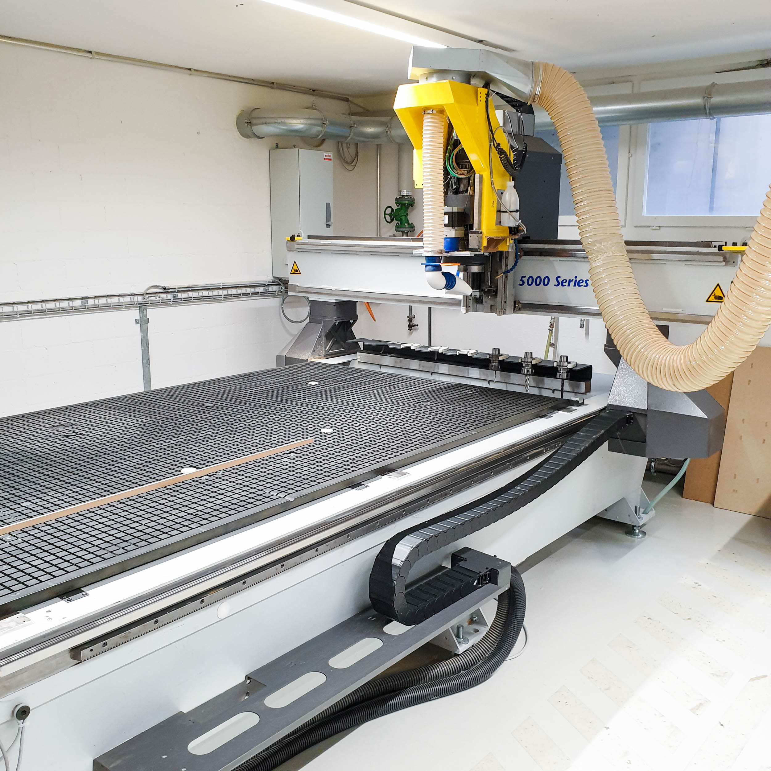
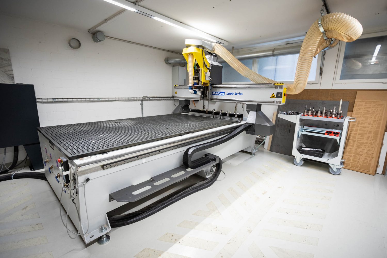
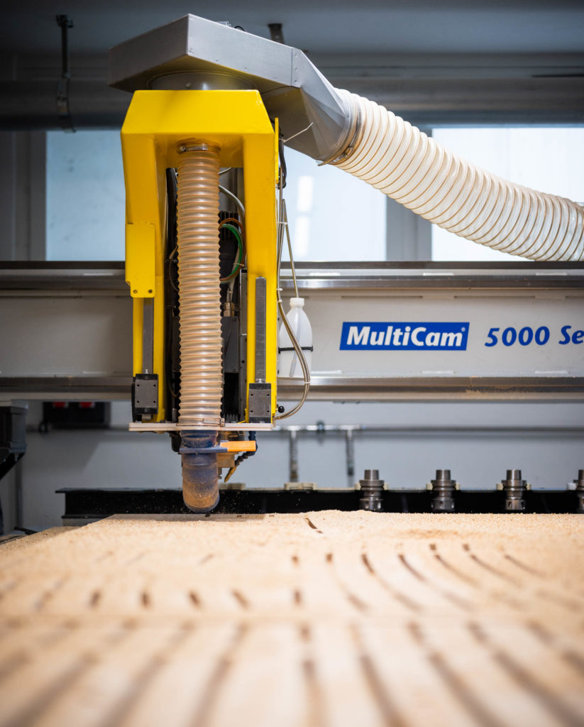
Fläche: 2500mm x 1500mm Höhe: 300mm Kosten 60CHF pro Stunde
Fräsvorbereitungen in Fusion 360
Teil zeichnen oder stl importieren (Z Achse zeigt nach oben)
Wechsel von Design in den Manufacture Tab
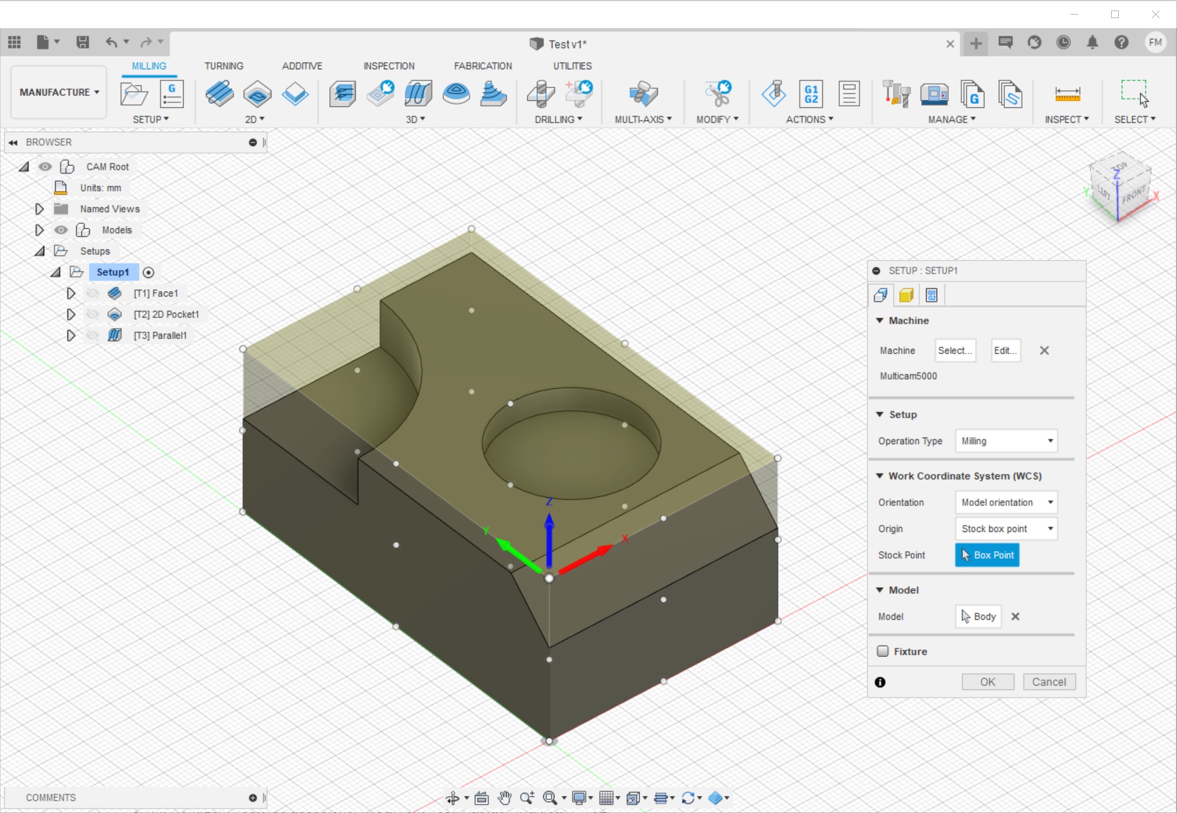
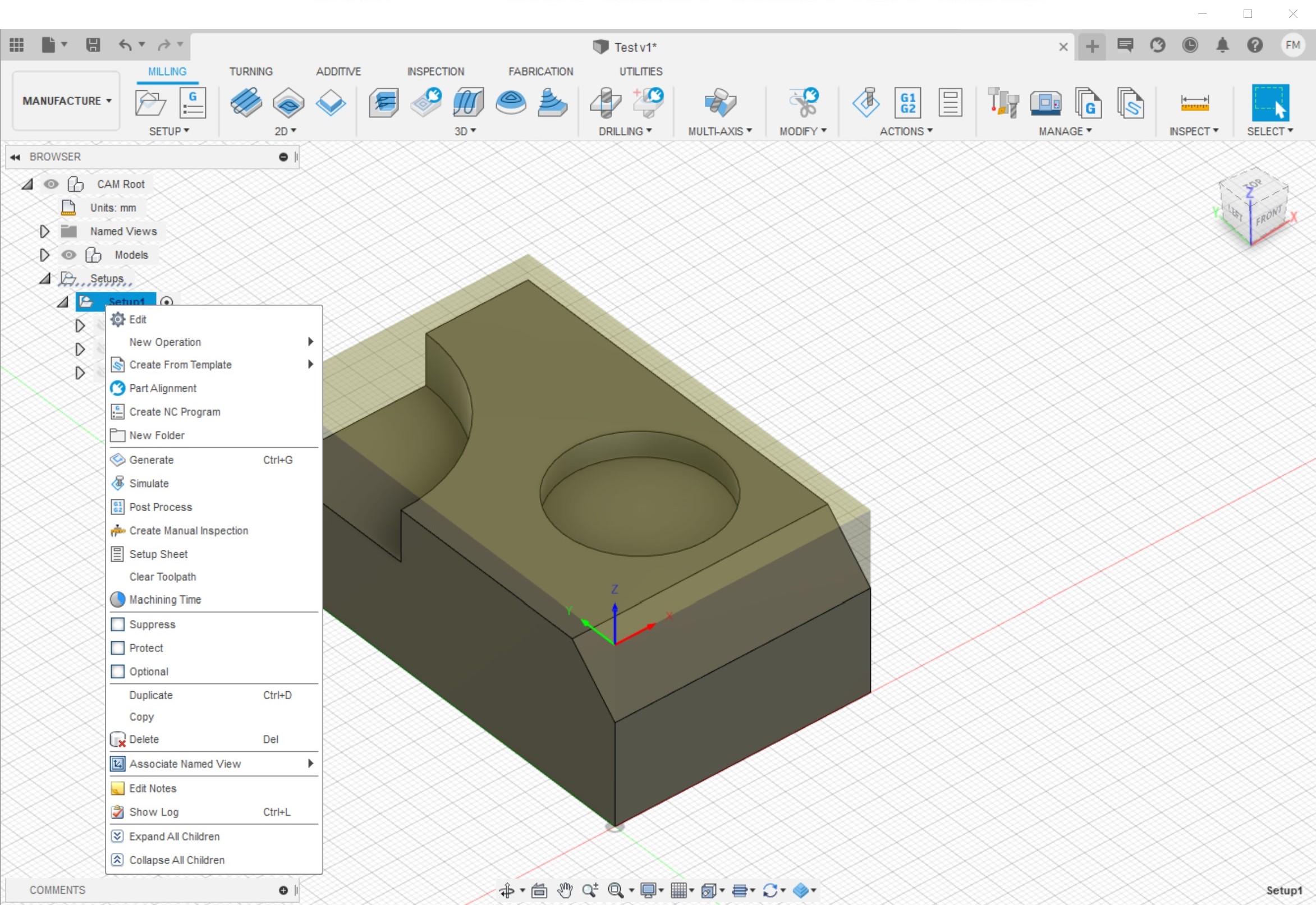
Setup erstellen und Maschine auswählen sowie Nullpunkt gemäss Screenshot auswählen.
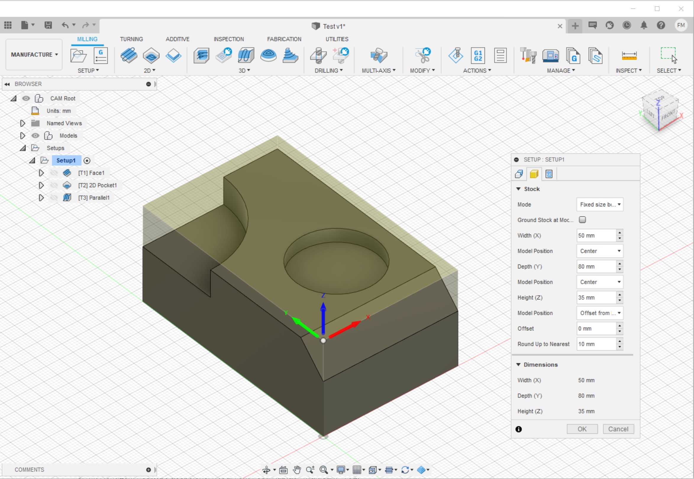
Grösse des Materials und Position des Teiles im Material eintragen.
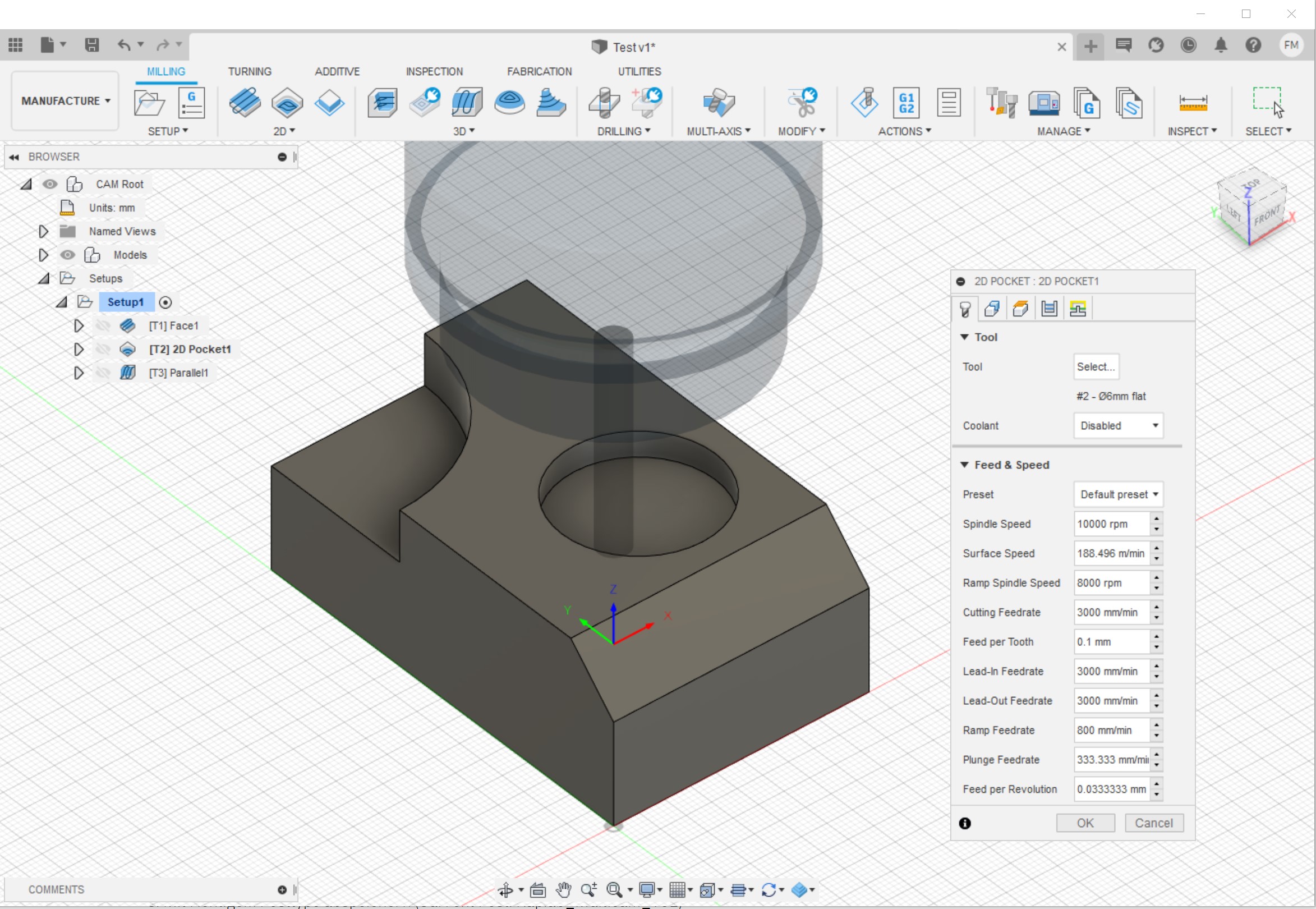
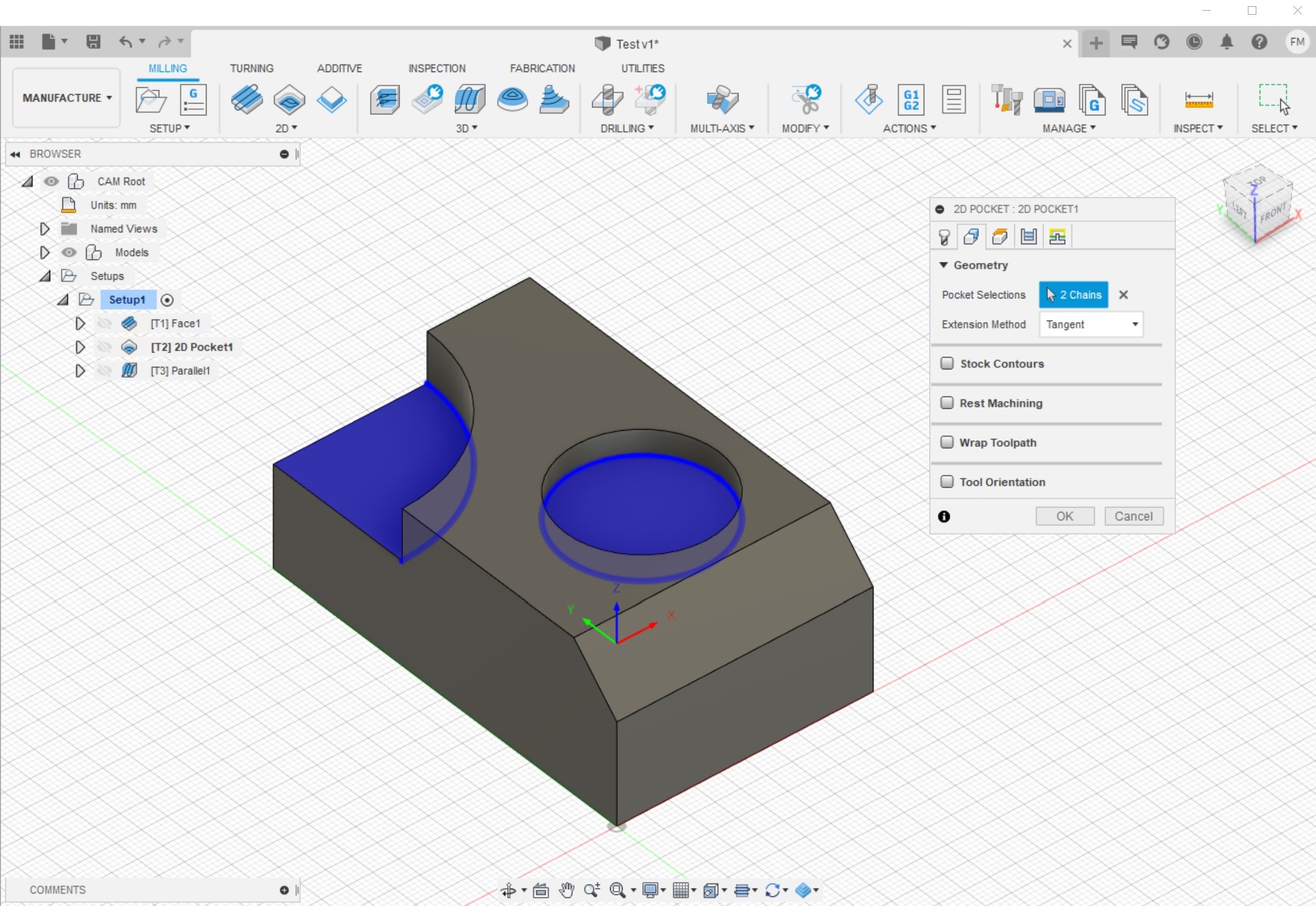
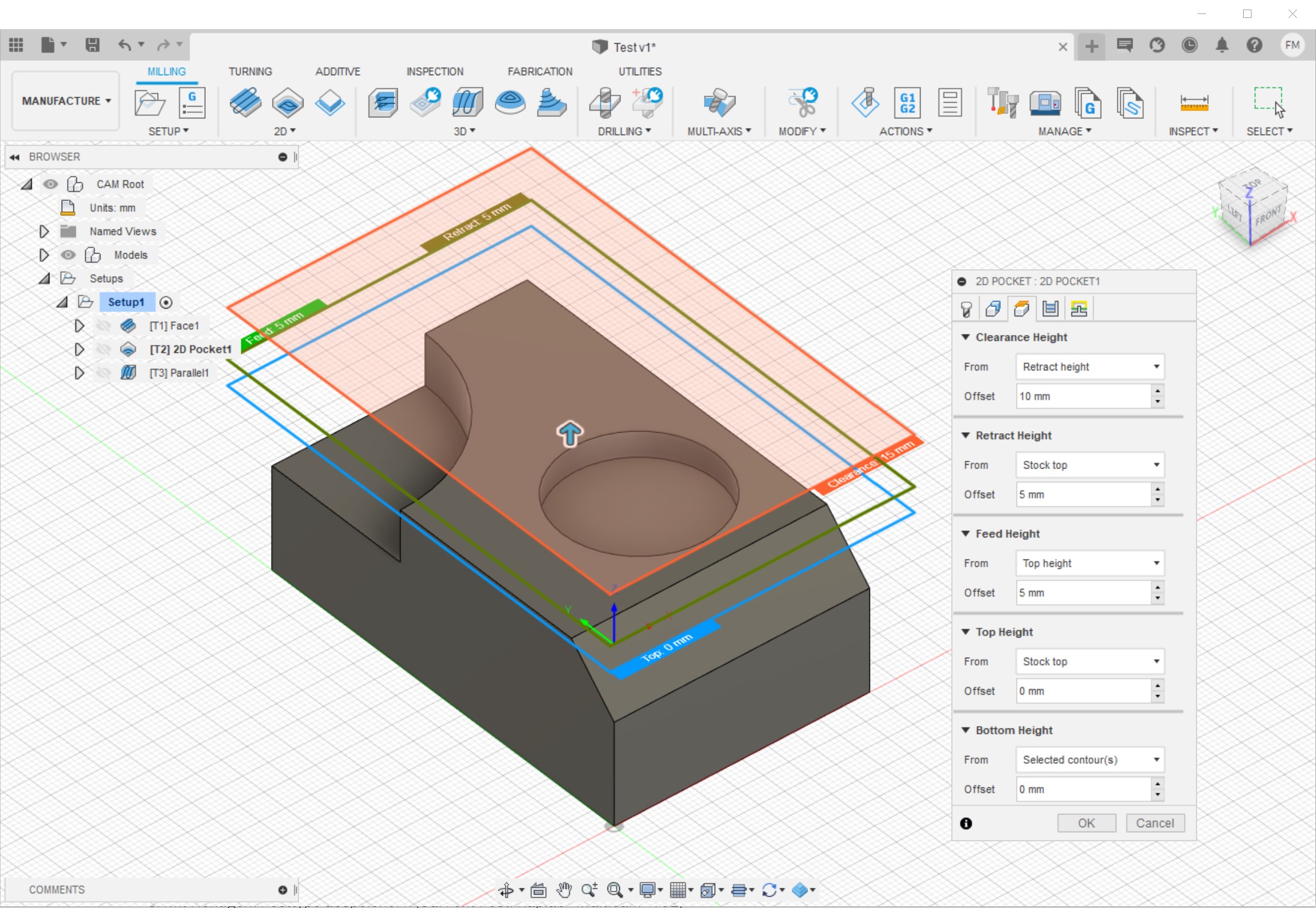
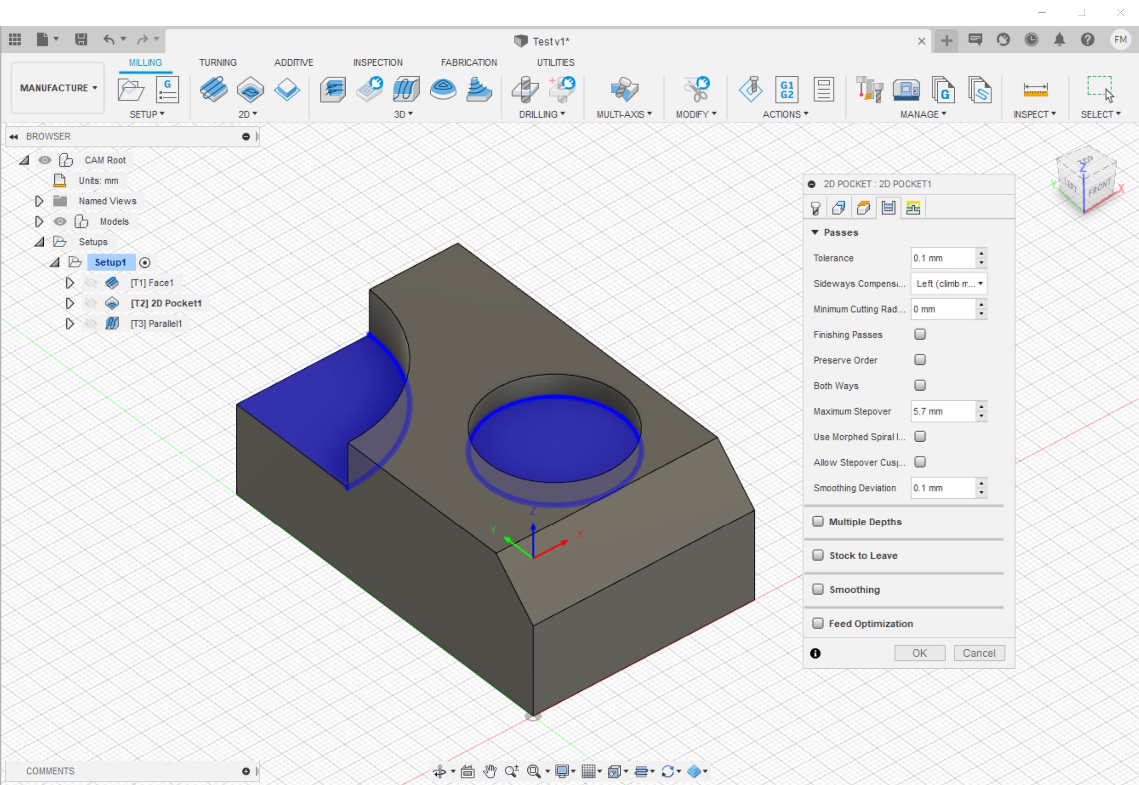
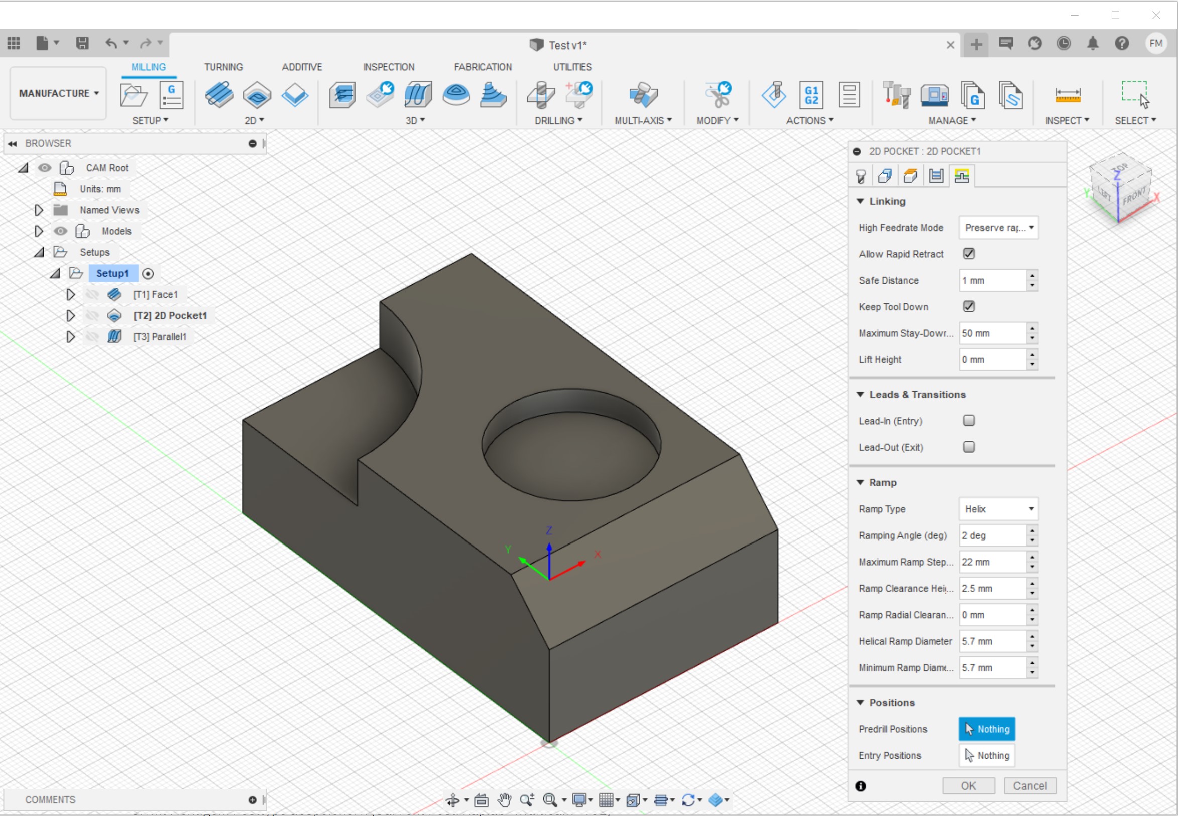
Bearbeitungsschritte hinzufügen und die Einstellungen in den jeweiligen Tabs definieren. Je nach Bearbeitungsschritt unterscheiden sich die Tabs ein wenig und es müssen unterschiedliche Einstellungen getätigt werden. Auf den folgenden Screenshots sieht man ein Beispiel für eine 2D Tasche.
Region für die Tasche auswählen.
Clearance Height etc. muss meistens nicht angepasst werden. Überprüfe trotzdem, ob die einzelnen Höhen Sinn ergeben.
Stepover auswählen: Je nach Material und Fräser
Multiple Depths: Je nach Material und Fräser
Stock to Leave: Wenn Material in der axialen oder radialen Achse stehen gelassen werden sollte
Lead-in und Lead-out deaktiveren (generiet falsche Höhen).
Ramp Type wählen: Je nach Fräser und Material
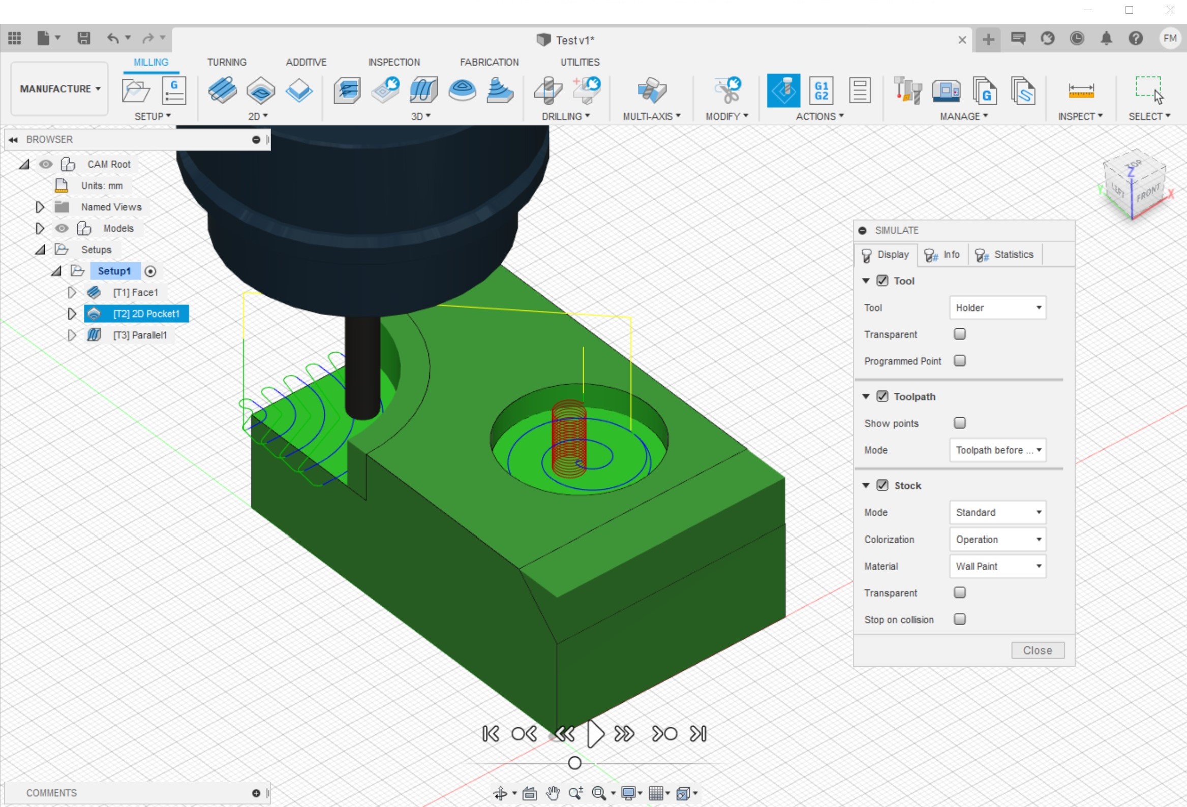
Simulation durchgehen und auf mögliche Fehler überprüfen.
Werden Anpassungen bei den Einstellungen vom Werkzeug gemacht (Drehzahl, Vorschub, Grösse) muss das Werkzeug bei den jeweiligen Features nochmals neu ausgewählt werden, damit die Änderungen übernommen werden.
G-Code erstellen (rechte Maustaste auf Setup oder auf einzelnes Feature) und auf den PC transferieren.
Fräsen (Vorbereitung)
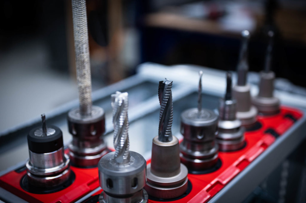
Werkzeug einspannen oder kontrollieren
Werkzeuge in vordefinierter Reihenfolge in Werkzeughalter positionieren
Fläche für Werkstück mit Gummiband vorbereiten
Öffnungen auf Maschinentisch für Vakuum abdecken/öffnen
Werkstück auflegen. Ev. mit Opferplatte darunter
Computer einschalten
Fräse Einschalten sobald PC aufgestartet ist (Hauptschalter beim Schaltschrank)
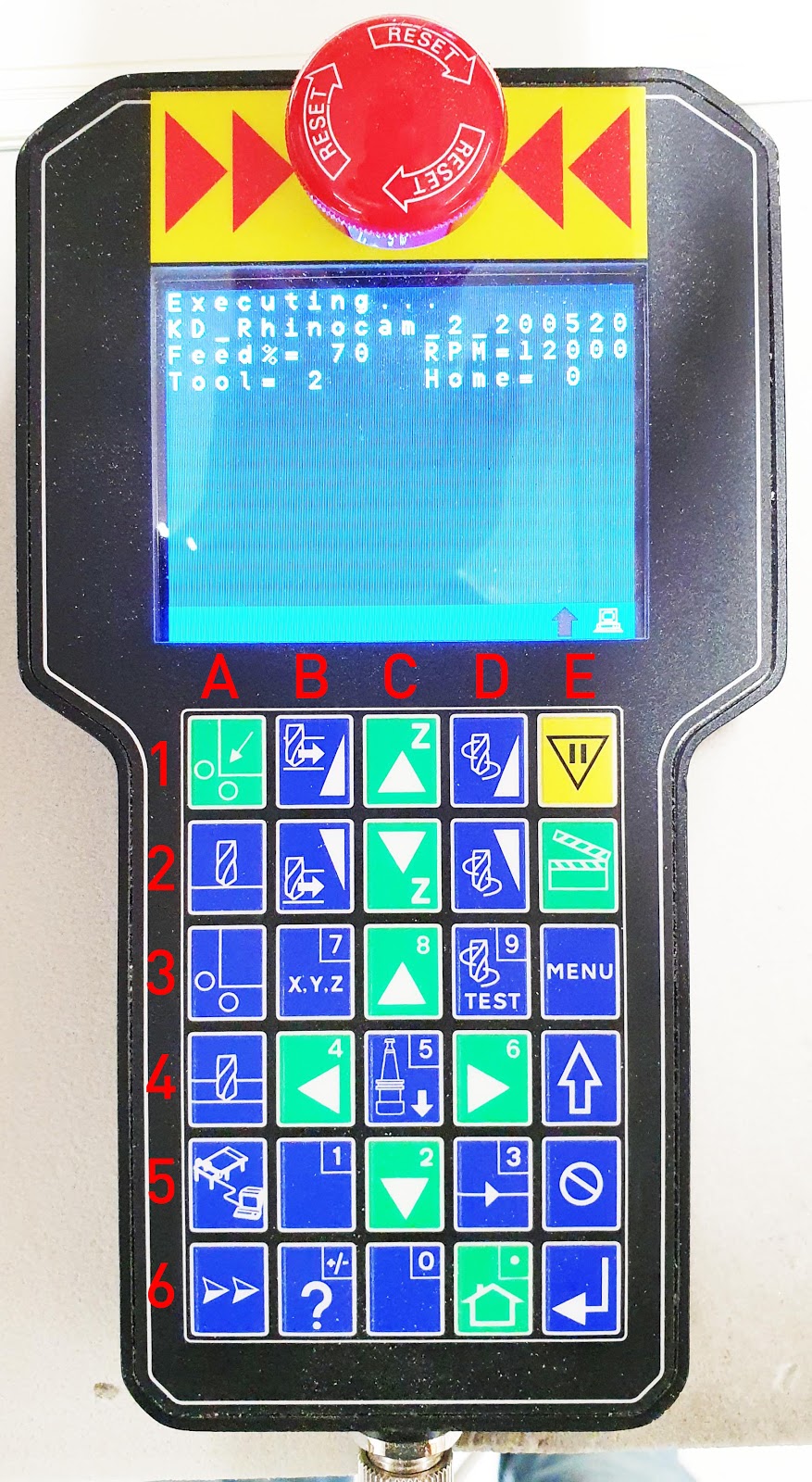
Maschiene “Homen” mit D5 (shift) und A1 – Bewegungsfreiraum beachten
Warm up? Mit E5 (Esc) überspringen
Vakuum mit Fusspedal einschalten
Gewünschte Vakuumzone mit Ventil aktivieren
Vakuum überprüfen
Werkzeuge Nullen
C5
ATC (Automatic Tool Change)
Calibrate Tool
E6
Tool zu kalibrieren auswählen
E6
Grounding Clip bei Werkzeug montieren
Werkzeug im Z über Kalibrieroberfläche fahren (C2)
0 halten für AutoSet
Esc um Kalibrierung zu verlassen (E5)
Grounding Clip entfernen
Enter (F5)
Für alle Werkzeuge repetieren
Werkstücknullpunkt
Nullpunkt anfahren (Mit A6 kann Geschwindigkeit der Achsen verändert werden)
A2 für Z achse
ZWEI MAL ENTER, um zu bestätigen
A3 für X und Y Achse
Enter zum Bestätigen
Tiefster Punkt setzen
Tiefstmöglicher Punkt anfahren
A4
Enter zum bestätigen
Mit A1 Nullpunkt überprüfen
Absauganlage Einschalten (Schalter oben links beim Schaltschrank, Auto)
Fräsen
Taste A5 um mit Computer zu verbinden
.nc Datei suchen
Mit Enter bestätigen
Vorschau mit E2 Bestätigen
E2 zum bestätigen
Am Fräsen
Bereitschaft zum Abbruch mit E1
Vorschub mit B1 und B2 anpassen
Drehzahl mit D1 und D2 anpassen
Ausschalten
Vakuum ausschalten
Druckluftzufuhr ausschalten (Bei der Spindel)
Menu (E3)
Shut Down, Enter (E6)
Bei Meldung “ready to shut down” Hauptschalter am Schaltschrank bedienen.
Aufräumen und Putzen
Abluft ausschalten
Fräsen mit Rhino
Vorbereitung allgemein
Rhino-Datei ist erstellt mit dem Preset “Small Objects in mm”
Konstruktion ist gemäss Screenshot orientiert (X und Y positiv, Z negativ)
Plugin Rhino CAM installieren
Fräsvorbereitungen in Rhino
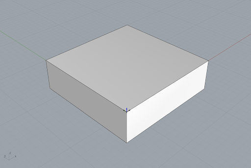
Mit Befehl BOX Grundmaterial erstellen
Soeben erstelltes Volumen auswählen und als Stock-Material definieren
Grundmaterial ausblenden
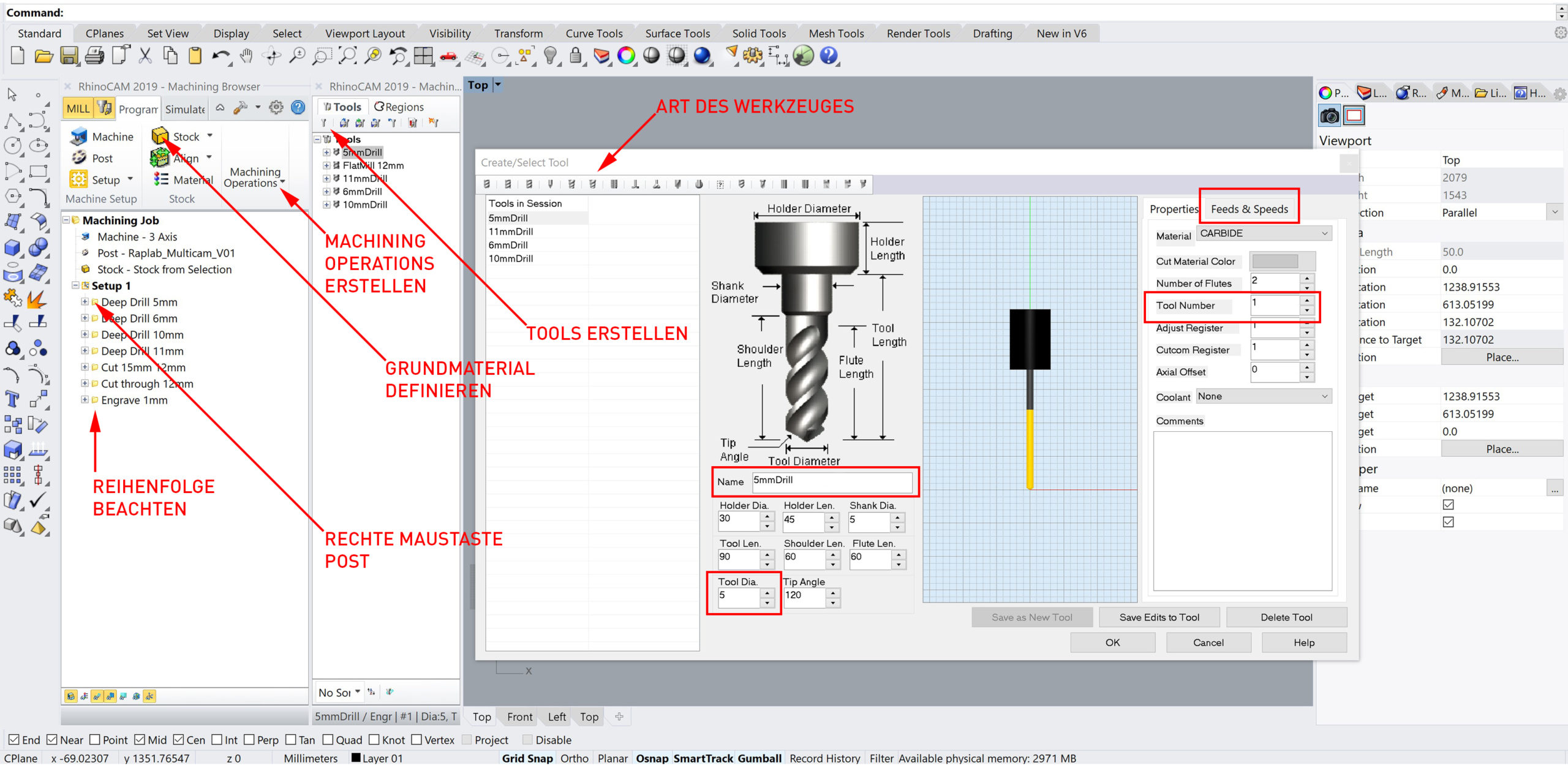
Tools erstellen (Art, Werkzeugnummer, Durchmesser, Drehzahl und Vorschub beachten)
Machining operations erstellen
Simulieren und überprüfen
Rechte Maustaste auf einzelne oder mehrere Operationen, Post
Mit richtigem Posttype abspeichern (Current Post: Raplab_Multicam_V01)
Ev. .nc Datei kontrollieren
Abspeichern und auf PC neben Multicam transferieren
.nc Datei in Ordner kopieren (DncFiles/Router/Posts/Name)