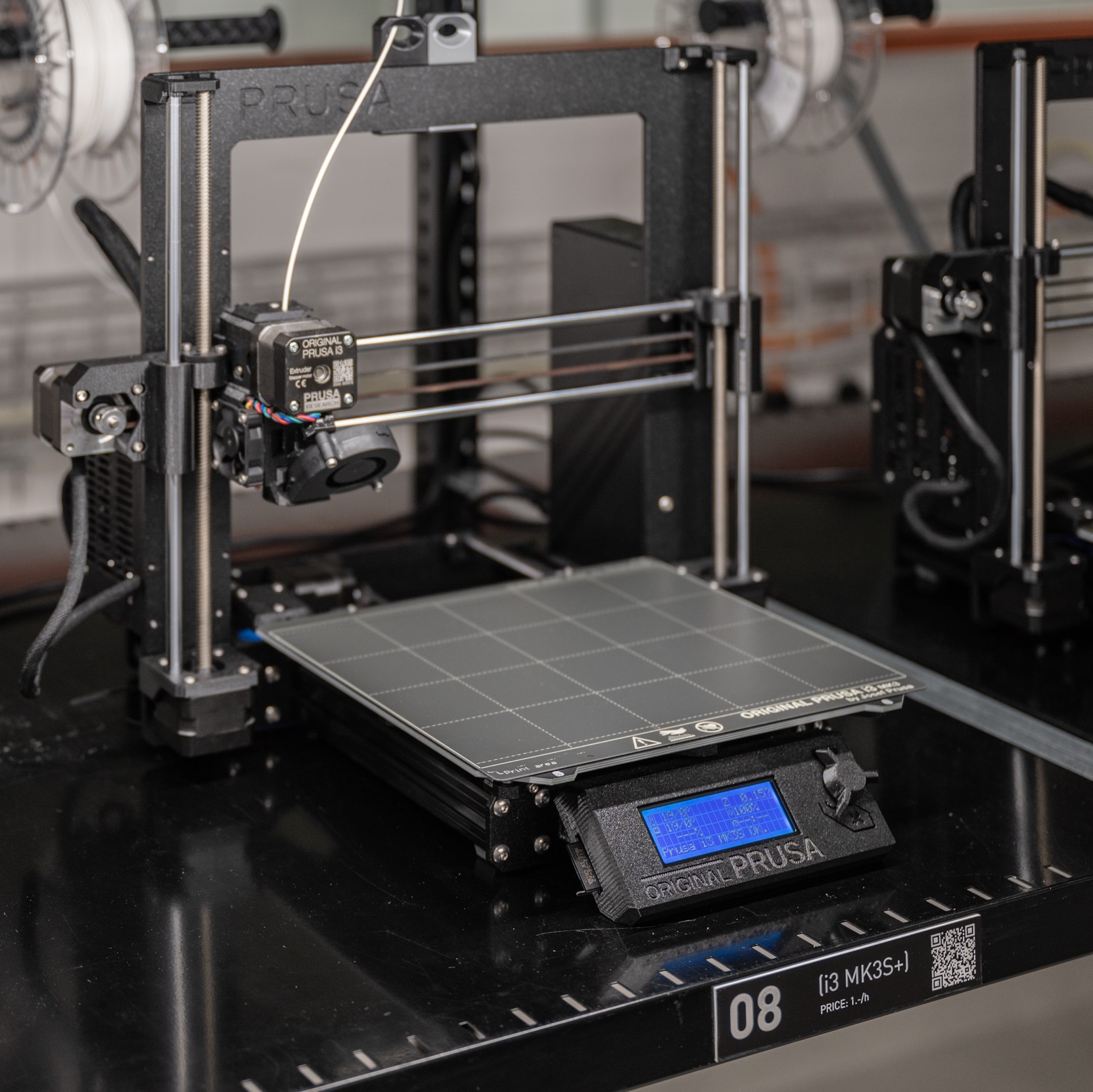
FDM 3D printing offers currently the best value in model and prototype making due to its relative ease of use, speed, print quality, and price. Depending on the application it can either be seen as a technique for drafting or for making functional parts, giving the user a wide range of possibilities. FDM is a process whereby a heated extruder deposits the first layer plastic onto a build plate and the successive layers onto the one previous. At the Raplab we have our printers set up with white PLA only.
Pros
A very inexpensive process
Machines are very affordable and therefore easily accessible
Print time can be rather quick if done in a considered way
The print material, PLA, is recyclable
Cons
Requires support material on overhanging parts
Layer height is usually larger than other print methods giving visible lines on the print surface.
Unable to achieve a super high level of detail
May not produce extremely complex structures due to the amount of support material required.
File Preparation
The File format most commonly used in 3d printing slicer software is an STL mesh, which is a representation of a 3-dimensional surface in triangular facets. This file format contains information about the inside and outside of the 3d model. Therefore, it is important when exporting a 3d model to STL, that the model is completely closed, solid or “watertight”. Otherwise, the software won’t be able to distinguish which part of the model is inside or outside during the export. Thus, unable to know where to place the infill.
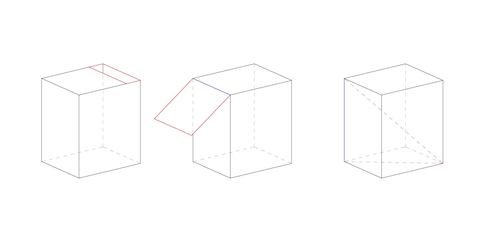
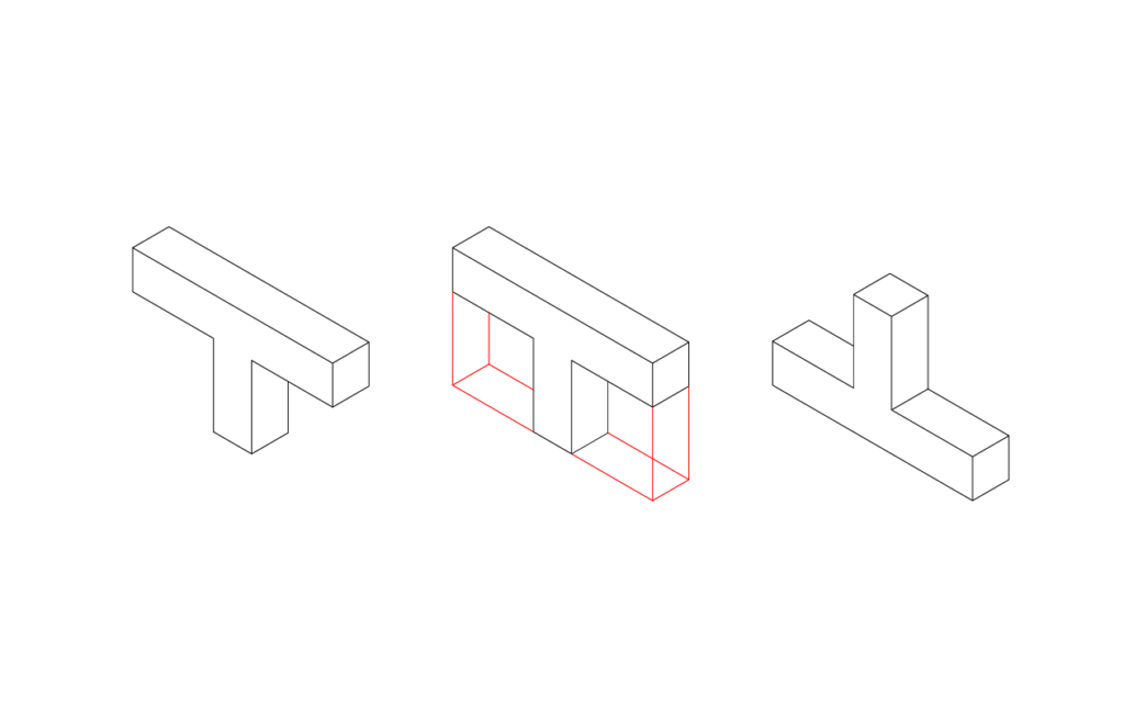
Below, naked edge and non manifold edge.
The model should have no manifold edges (blue). This is an edge should not be made up of more than 2 faces.
It also shouldn’t have any naked edges (red). A naked edge is made up of only one surface. If the model has a naked edge then it is by definition not solid or watertight.
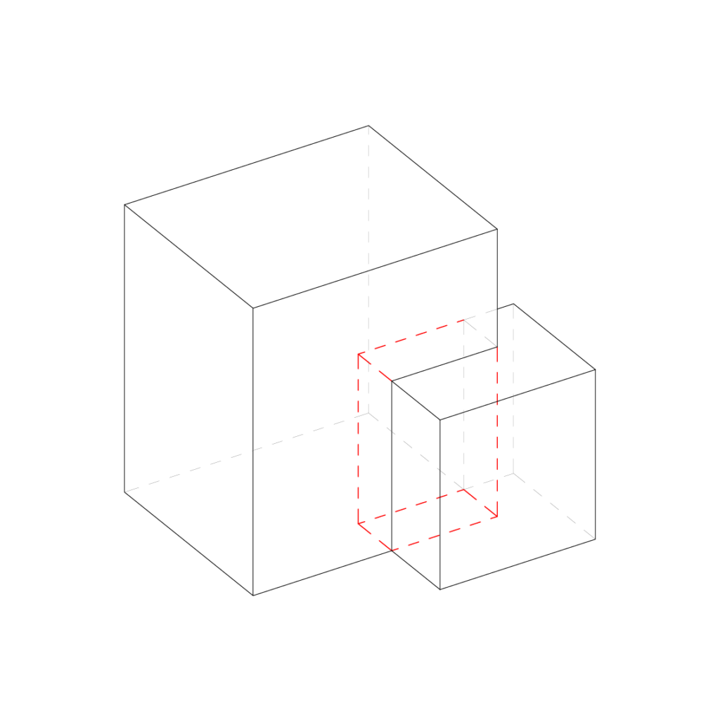
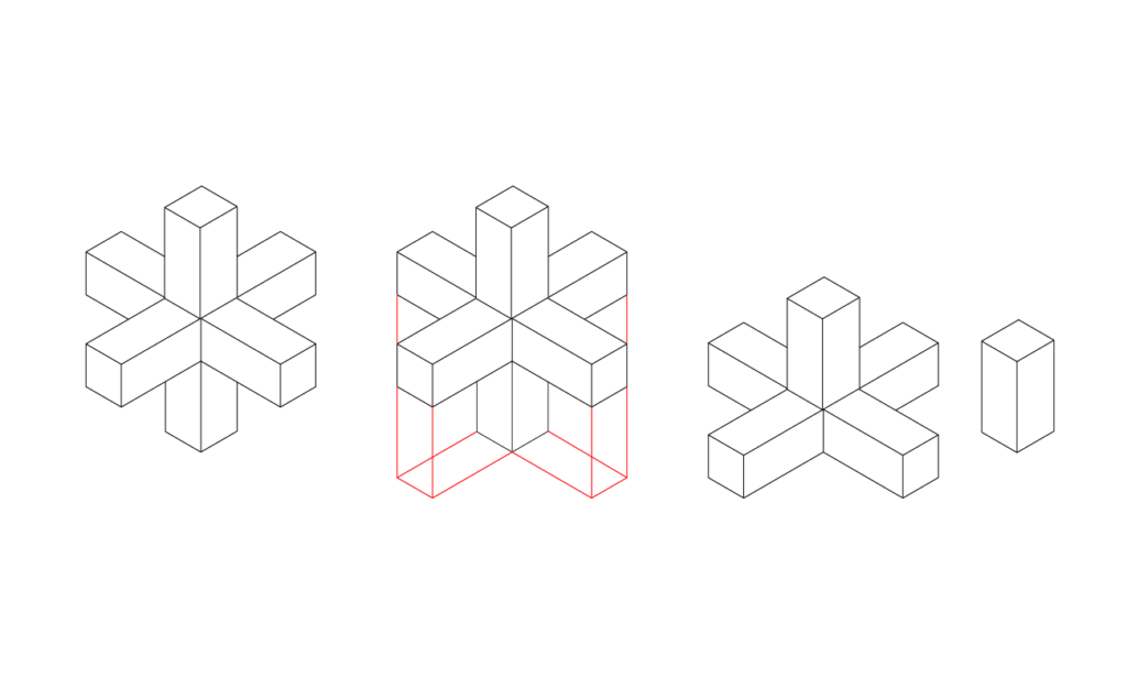
It is also very important that the 3d model doesn’t have any intersecting parts.
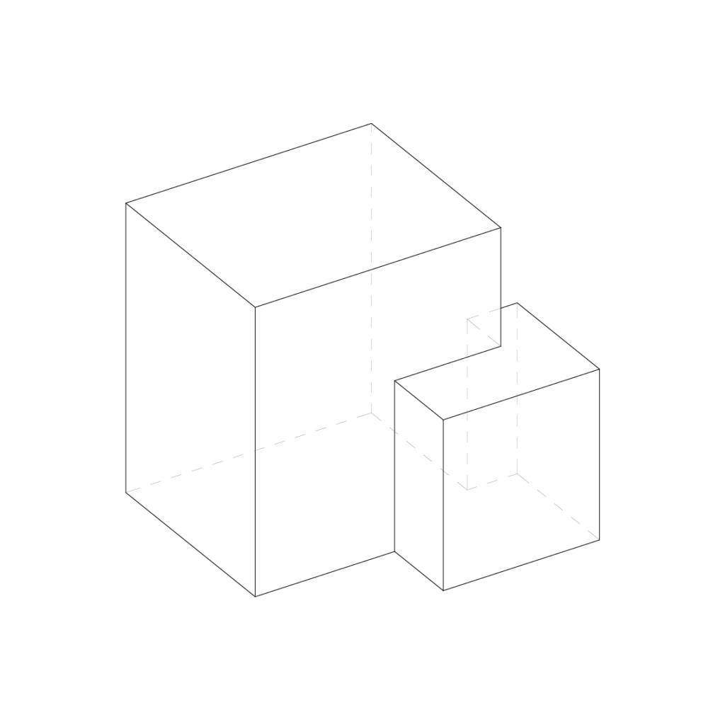
If you have more than one part, it is best practice to export them as individual STL files. This gives more flexibility when preparing the print in the slicer software. Multiple parts can then be arranged on the build-plate. The slicer will also automatically make all the bottom surfaces that are meant to be attached to the build plate co planar. So we don’t have to worry about where models are in the world coordinates
Export Checklist
The object must be a closed poly-surface or mesh
No non manifold edges or naked edges
No intersecting surfaces
Individual parts should be exported separately
The model must be smaller than the printers build area – It can be split if necessary
Rhino tip – Check edges by using the command “show edges”. Then the box’s naked edges.
Slicer Software Guide
Understanding the limitations of the machine and how to get the most out of it will allow for some very effective results. Here we will outline some 3D printing terminology as well as giving tips and tricks to help reduce time and increase print quality.
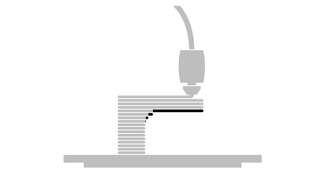
Overhang
FDM 3d printing is a process in which a layer of extruded plastic is placed on top of the previous one. Each new layer must be supported by the one beneath it. If the next layer extends outside the boundary of the previous one, this is known as an overhang.
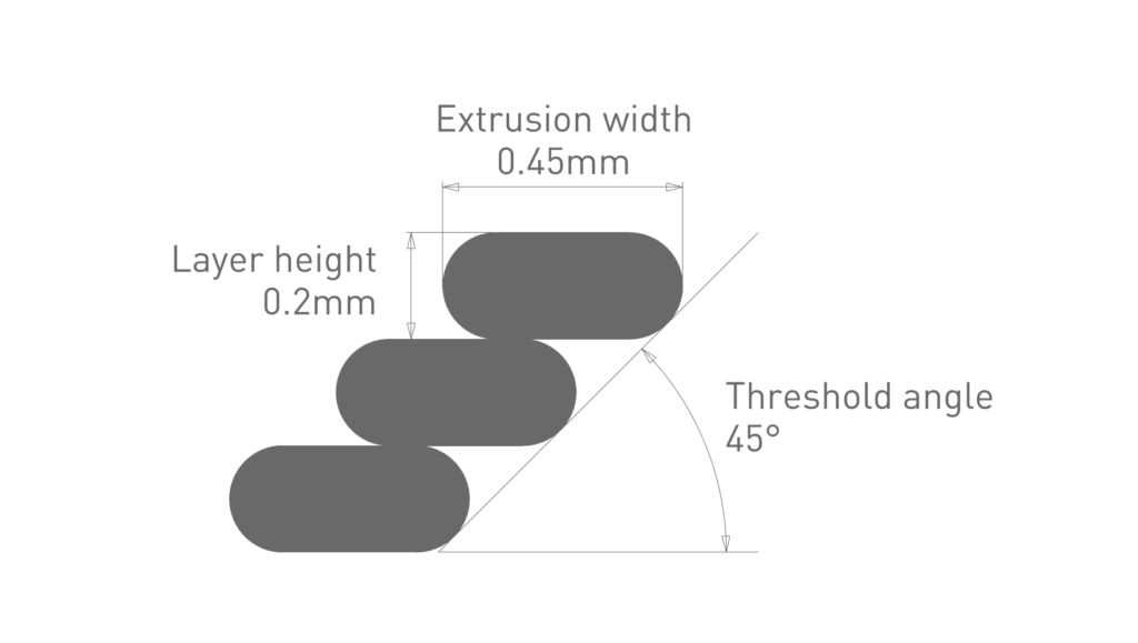
Threshold angle
Threshold angle is a term to describe the amount of overhang. The smaller the angle, the larger the overhang.
With the default settings of 0.2mm layer height with the 0.4mm nozzle, the extrusion width is 0.45mm. With these settings the printer is able to achieve an overhang of 45 degrees without the need for support material. This is because there is still just enough contact with the previous layer. If the angle decreases the print is likely to fail as there is not enough underneath to support it.
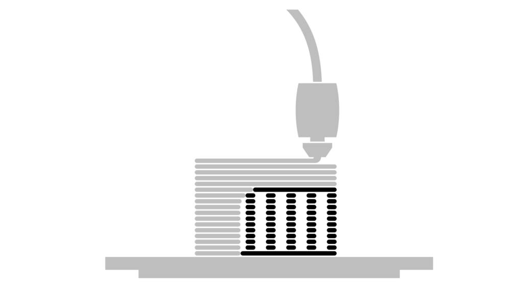
Support material
Support material is a printed structure, usually in a lower density than the supported object, so it can easily be broken off. There is also a slight offset from the object, so it doesn’t adhere too strongly. Support material is not waste and can be recycled.
However due to the nature of the process the surface quality of the part touching the support is compromised. Utilising support material also massively increases the print time and material used. Therefore, it should be avoided if possible.
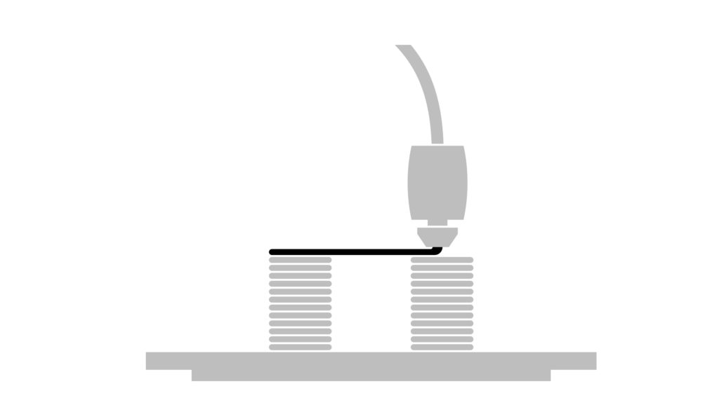
Bridging
Usually, it isn’t possible to print an unsupported layer without anything underneath to support it. Whether that be support material or the previous layer. If the toolpath of the unsupported part is going in one direction and is supported at either end, the printer can print in mid-air over short distances. This is known as bridging. The 3Dprinting slicer will automatically optimize the toolpaths to make this happen.
Avoiding support material
Flipping or splitting your part can remove the need for any support material. It may seem counterproductive splitting a model as it would then have to be glued together which means there is an extra step in the physical build. However in more cases than not, this approach makes a lot more sense in terms of reducing print time and improving print quality.
In the case of 3d printing we also want to have a large enough surface area attached to the build plate and splitting the model can often give us a larger surface area.
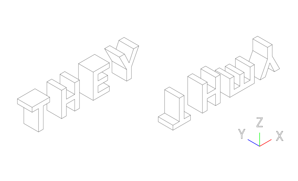
The “they” rule
Let’s imagine we want to print out the letters of the words THEY without support material 50mm high but we can only rotate them in the XZ orientation. For the purpose of the exercise, rotating in the YZ is impossible.
The letter T can be rotated 180 degrees so it is printed upside down.
The letter H does have an overhang. However this can be printed without support with bridging.
The E can be rotated 90 degrees.
And the Y would work fine as the threshold angle is greater than 45 degrees. However, it would be best to rotate 180 degrees to increase the amount of surface area attached to the build plate.
(Image of the normal orientation and the optimized orientation)
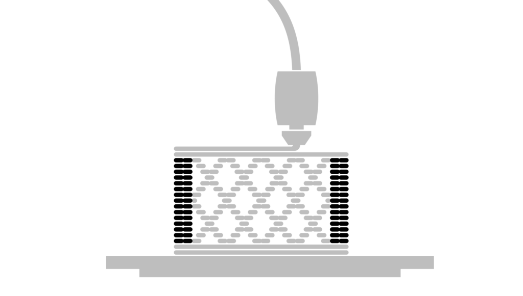
Vertical Shells
The vertical shells or sometimes named perimeters make up the vertical shells of your print. By default the slicer selects 2 layers.
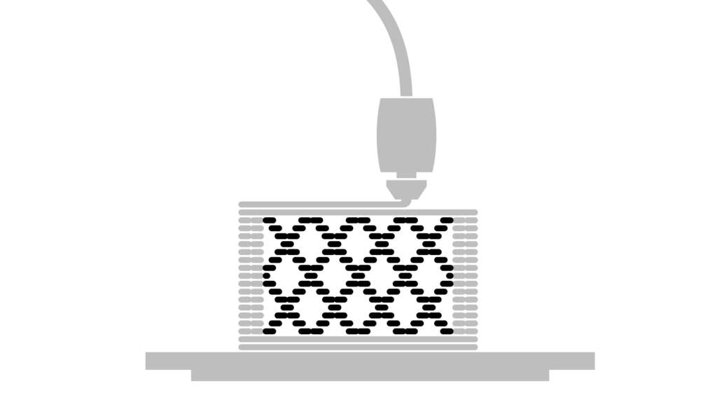
Infill
The part within the walls is called the infill. The purpose of the infill is to give the model some more strength but more importantly it’s there to support the top horizontal shells. Reducing the amount of infill can reduce the print time.
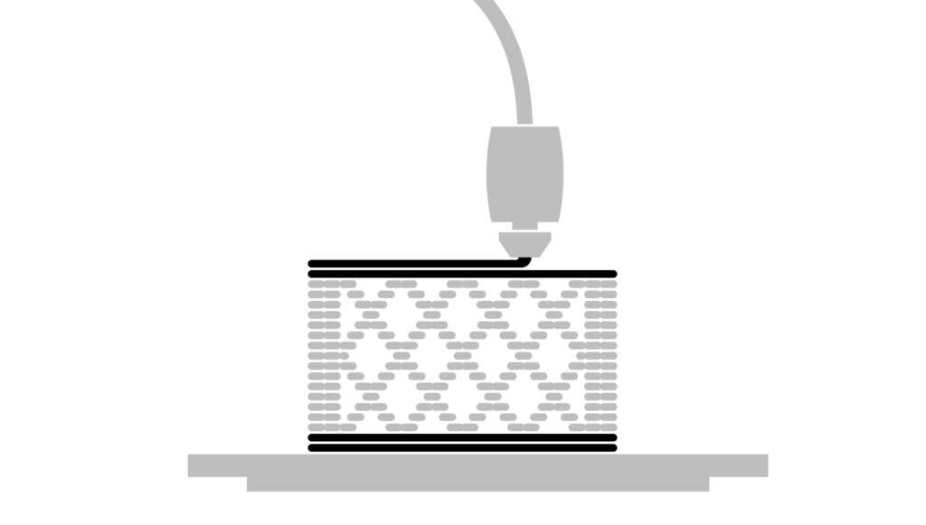
Horizontal Shells
The horizontal shells are the top and bottom layers of the print.
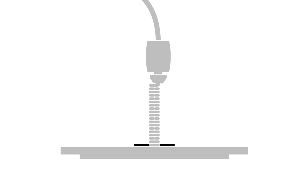
Brim
Sometimes the only option for printing an object will only allow for a small amount of contact to the print bed. In this instance it is best to use a brim to increase the contact area. This can be pealed off the model once printed.
Reducing Print time
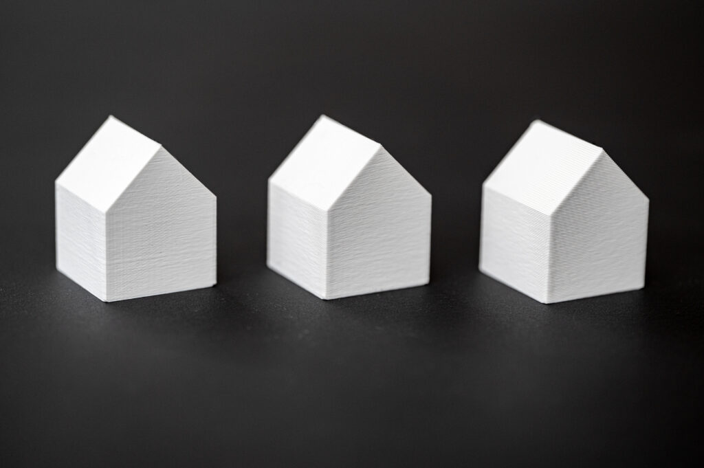
Increase Layer height
The most obvious way to reduce the print time is to increase the layer height. This will however give more prominent layer lines.
0.15mm – Layer Height – 52m
0.3mm – Layer Height – 28m
0.4mm – Layer Height – 22m
Spiral Vase
This removes one of the top horizontal shells and the infill from the model. It also prints a single perimeter in a spiral. It’s a good idea to use a slightly larger nozzle for this or adjust the print width in the advanced settings to 1mm.
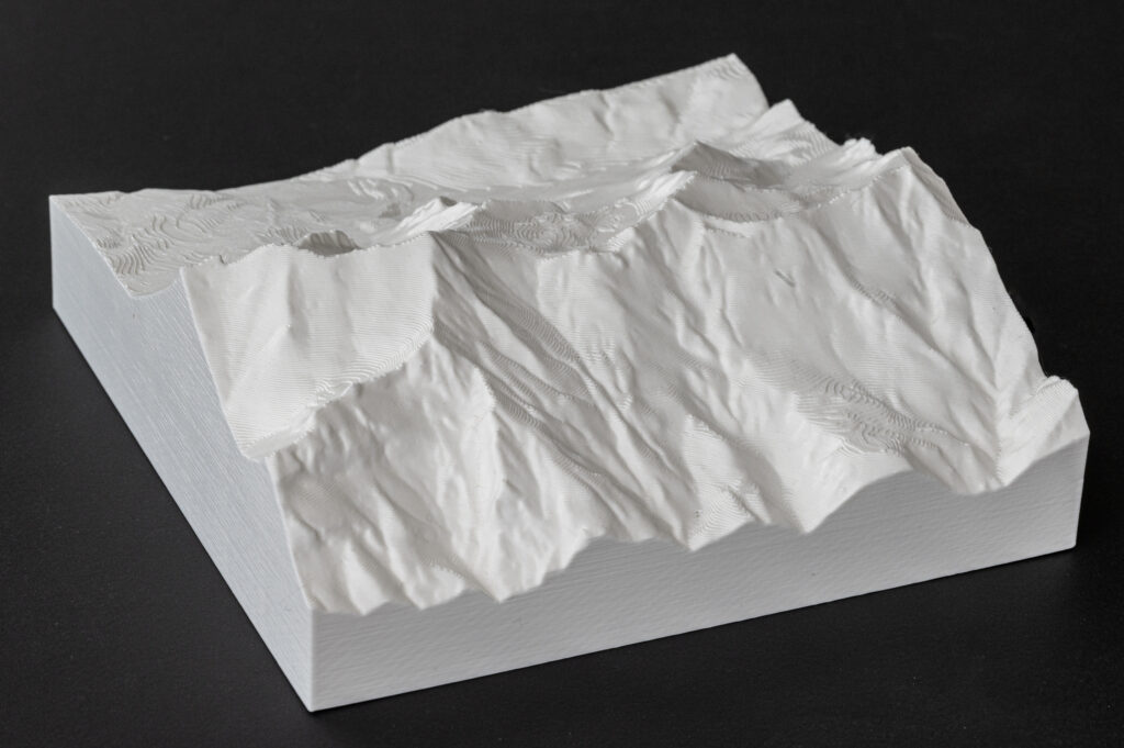
Normal print – Printed same orentation as the photo.
0.4mm Nozzle, 0.3mm Layer height and infill 5%
9h53m
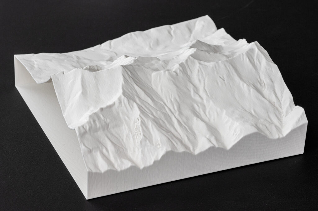
Spiral Vase print – Printed at 90 degrees to the orientation of the photo.
0.4mm Nozzle, 0.3mm Layer height
2h26m
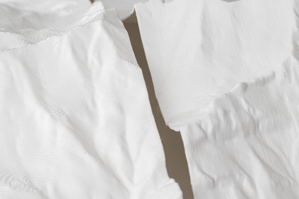
Tip – As the spiral vase print is hollow, it can be used as a mold for casting plaster.
Nozzles
At the Raplab we have the following nozzles:
0.4mm
0.6mm
0.8mm
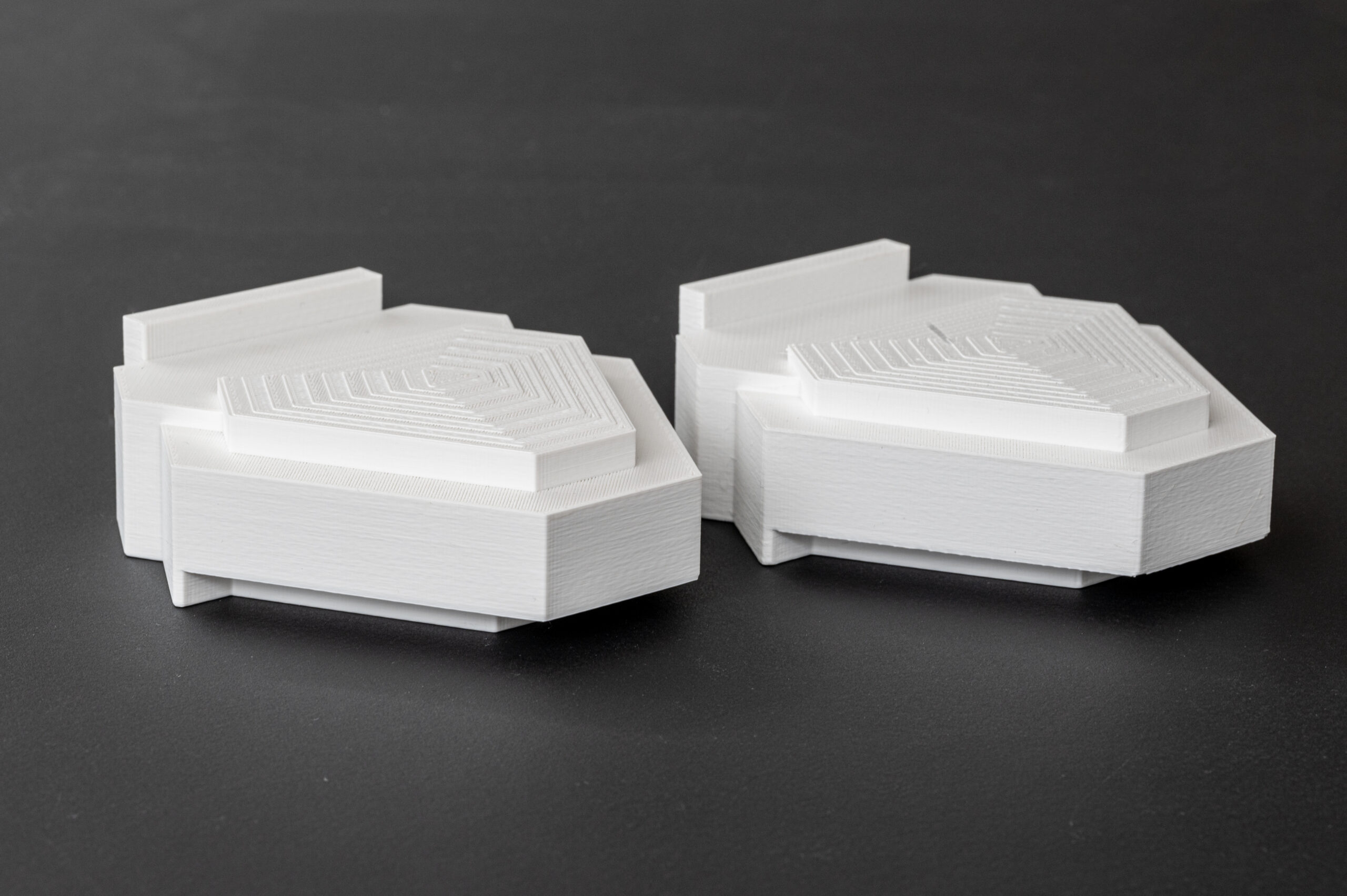
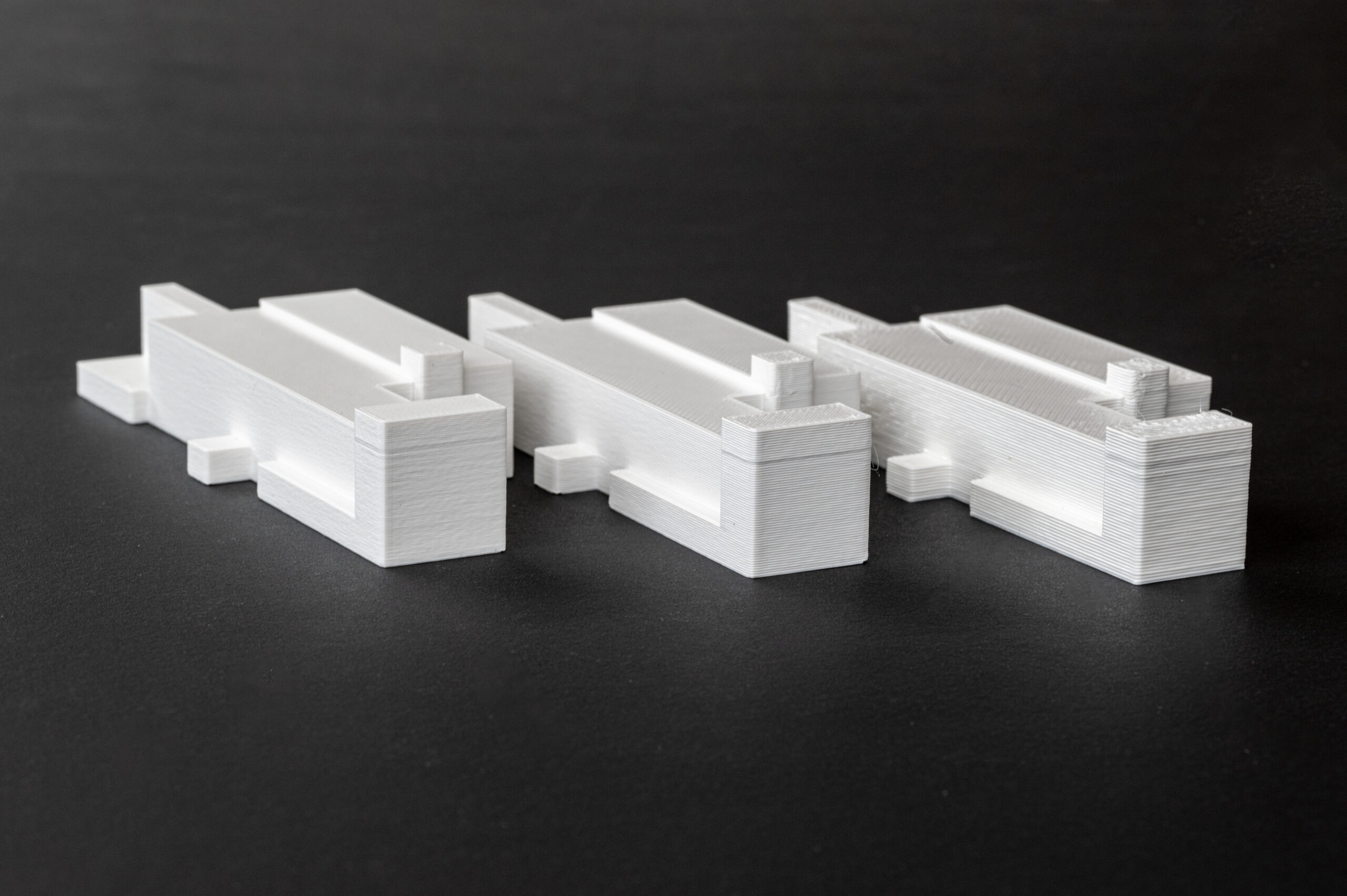
0.4mm Nozzle 0.3mm Layer Height 2h51
0.6mm Nozzle 0.3mm Layer Height 2h21
A larger nozzle size can reduce the print time with only a slight compromise on print quality. For example, a 0.6mm nozzle can achieve a 0.2mm layer height which is the default setting for the 0.4mm nozzle. The print width however is larger, reducing the print time quite a lot. The only difference in appearance is that it slightly softens the details in the XY orientation.
If a larger layer height is acceptable, then a larger nozzle will allow you to increase this even further than a standard 0.4mm nozzle. Which again, will decrease the print even more.