Hello! I’m glad you decided to enroll in this course. I’m Alessandro, the head of the Raplab and your course facilitator.
I will be your guide on this journey. Please email me directly at any point if you have questions or concerns.
We appreciate feedback, so if you notice anything about this course that could help improve your experience, don’t hesitate to mention it.
This course provides a basic overview of Raplab and the essential things you need to know to work in our workshops. By taking this course, you will start your journey of becoming an empowered model and prototype-making person.
Who is this course for?
This course is designed explicitly for BA, MA, and Ph.D. students, teaching staff, and employees of the Department of Architecture and other Departments at ETH Zurich.
What will I learn?
You will get an overview of the Raplab and its infrastructure
You will get to know how access, permissions, and introductions work
You will be able to find all vital information on our website
You will understand the potential and the limits of the Raplab
How do I complete the course?
It’s simple – carefully read the learning material and take notes to ask us questions if something is unclear.
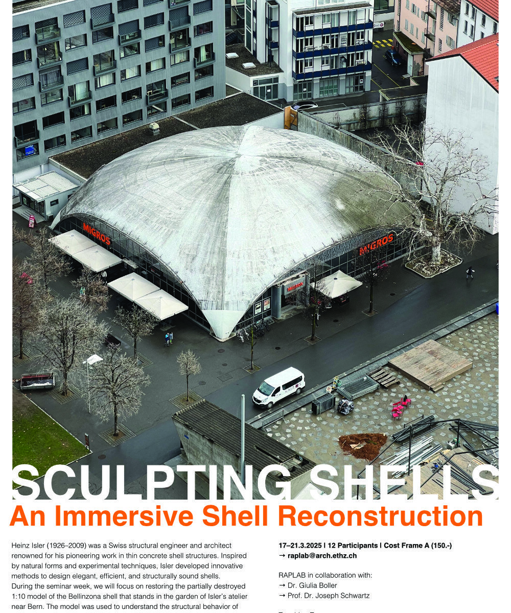
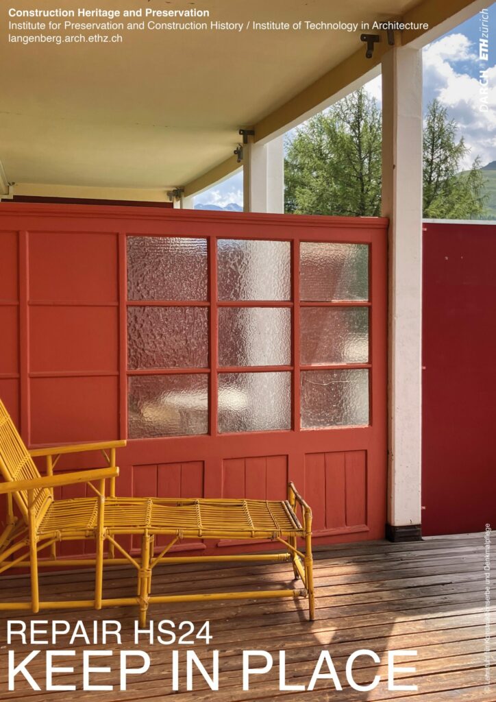
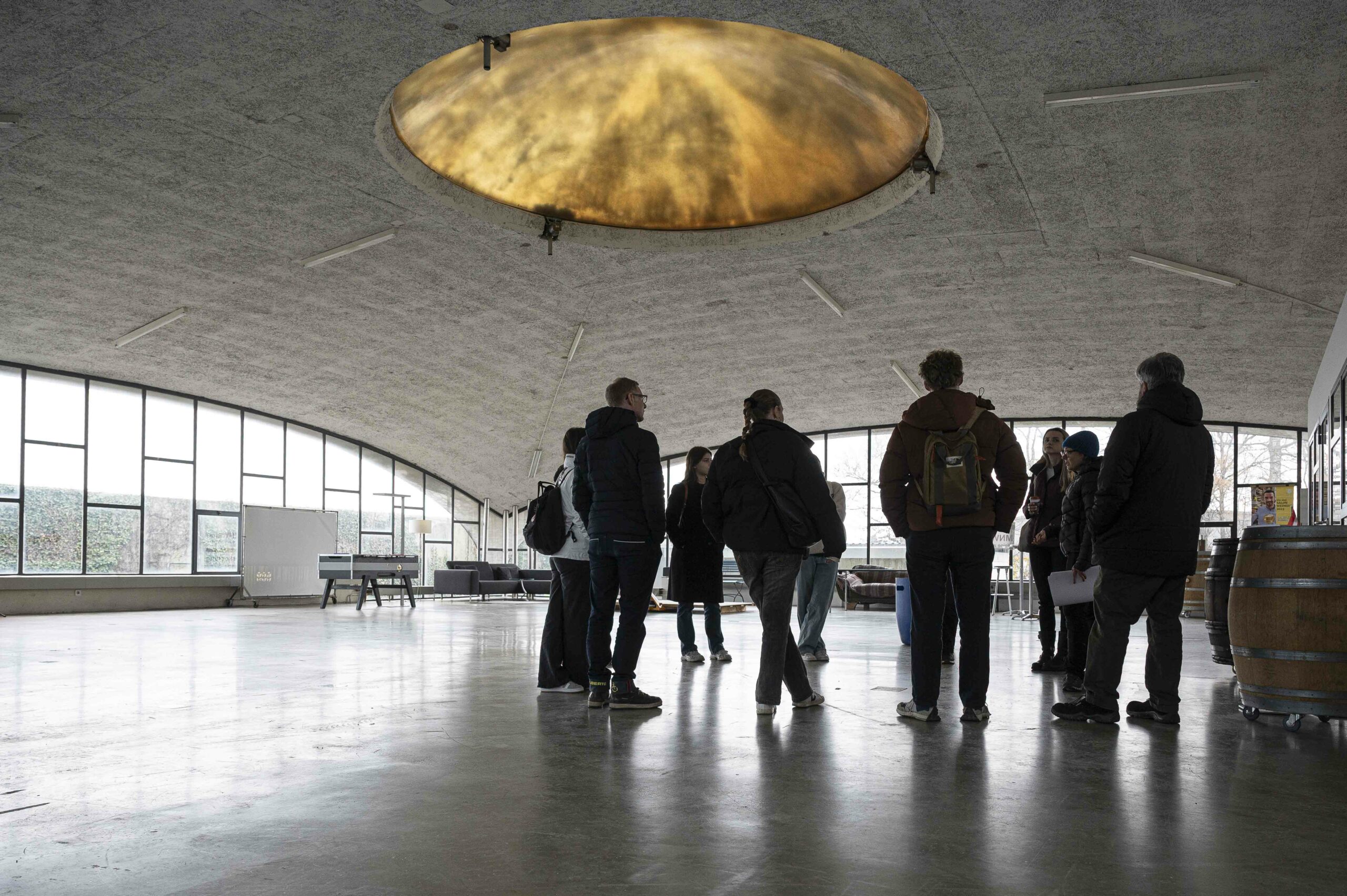
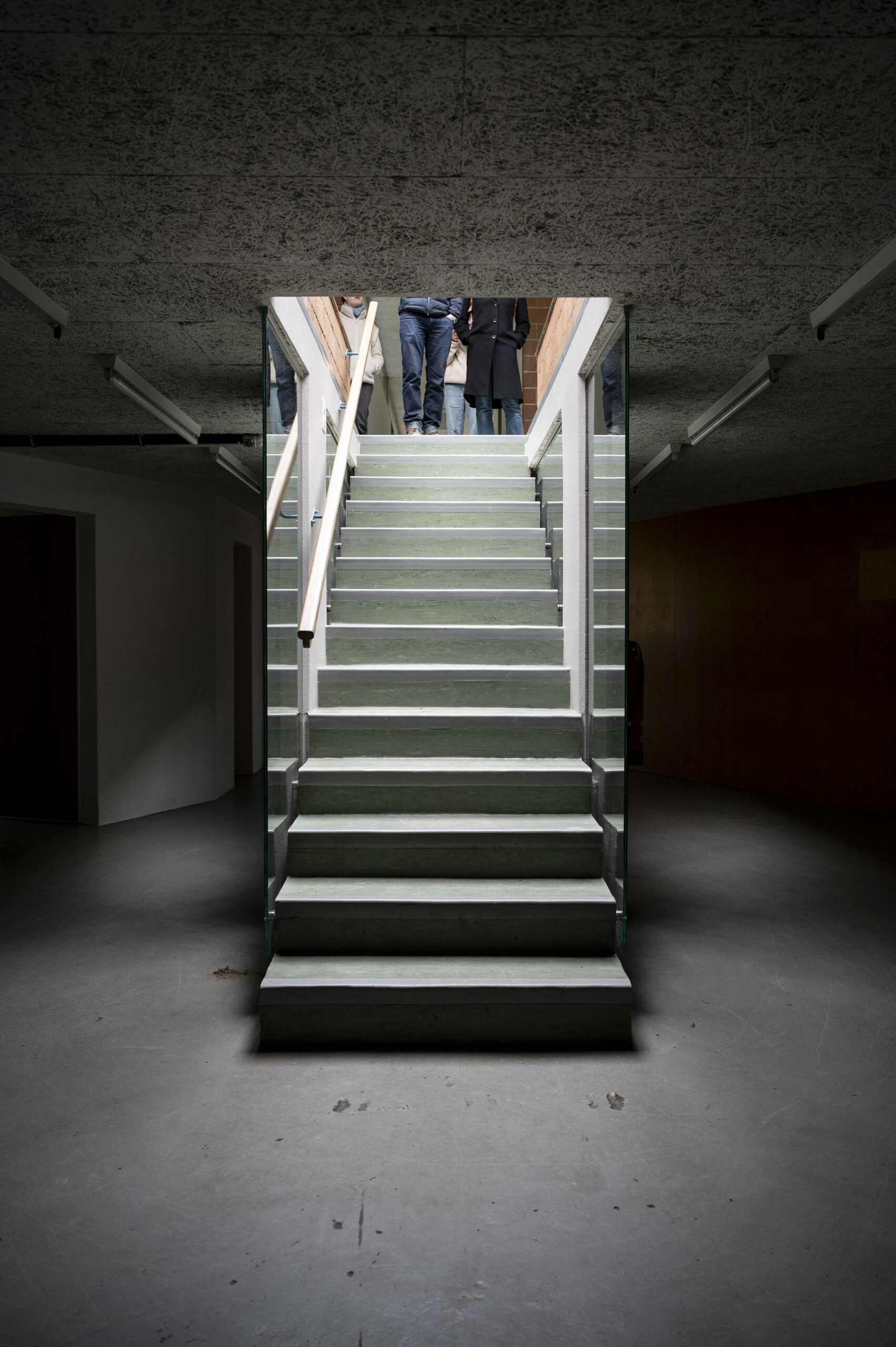
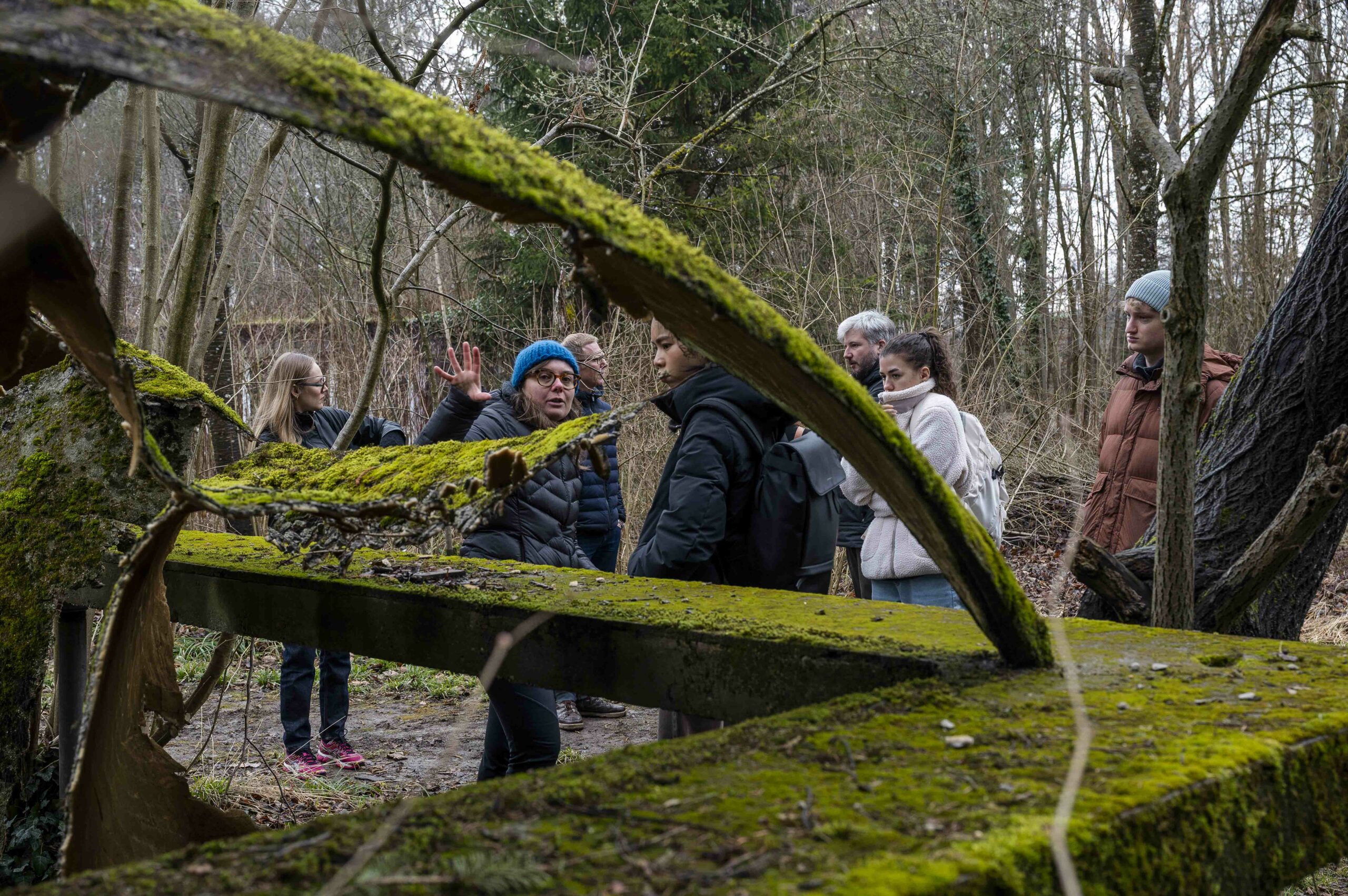
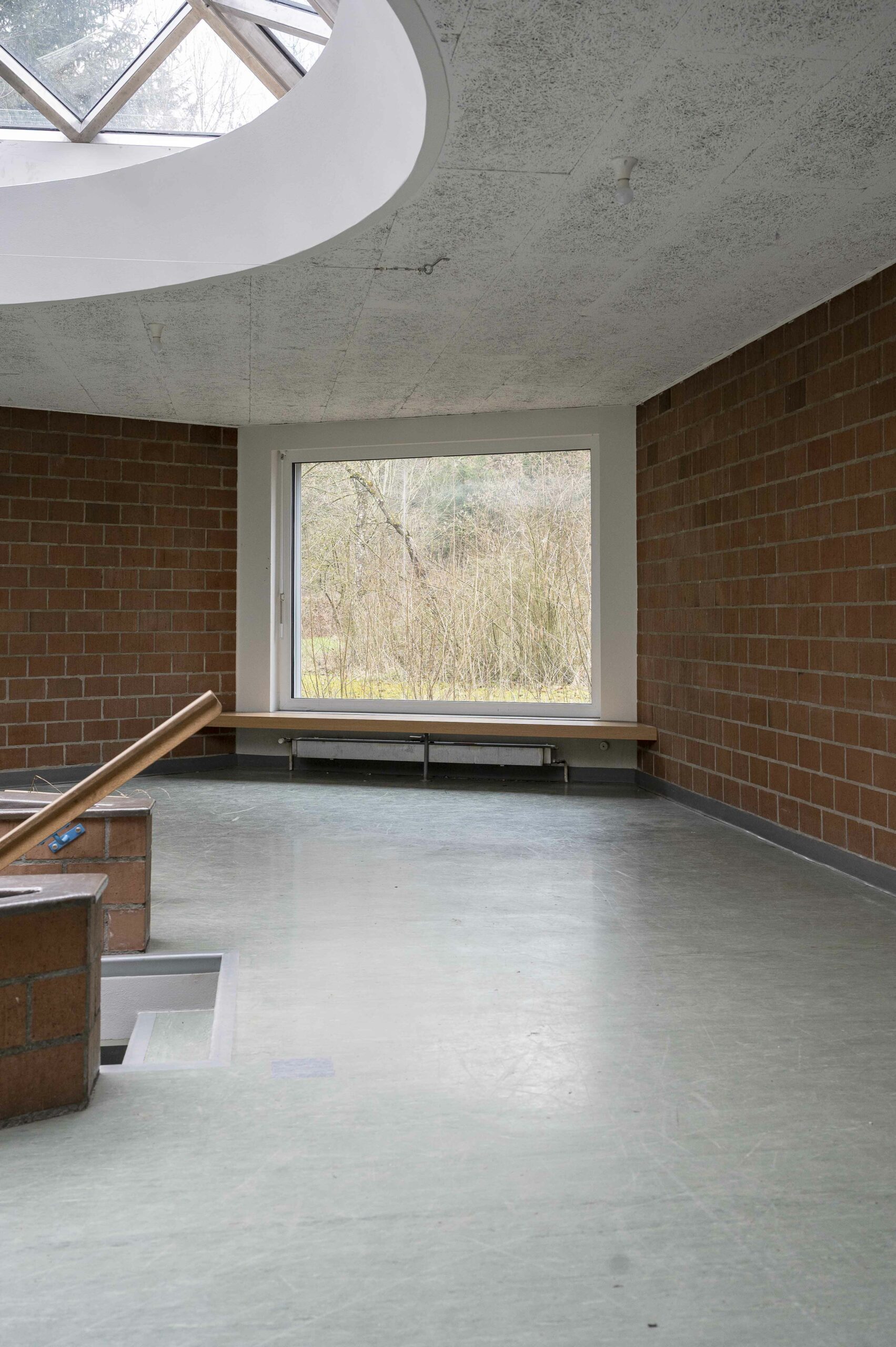
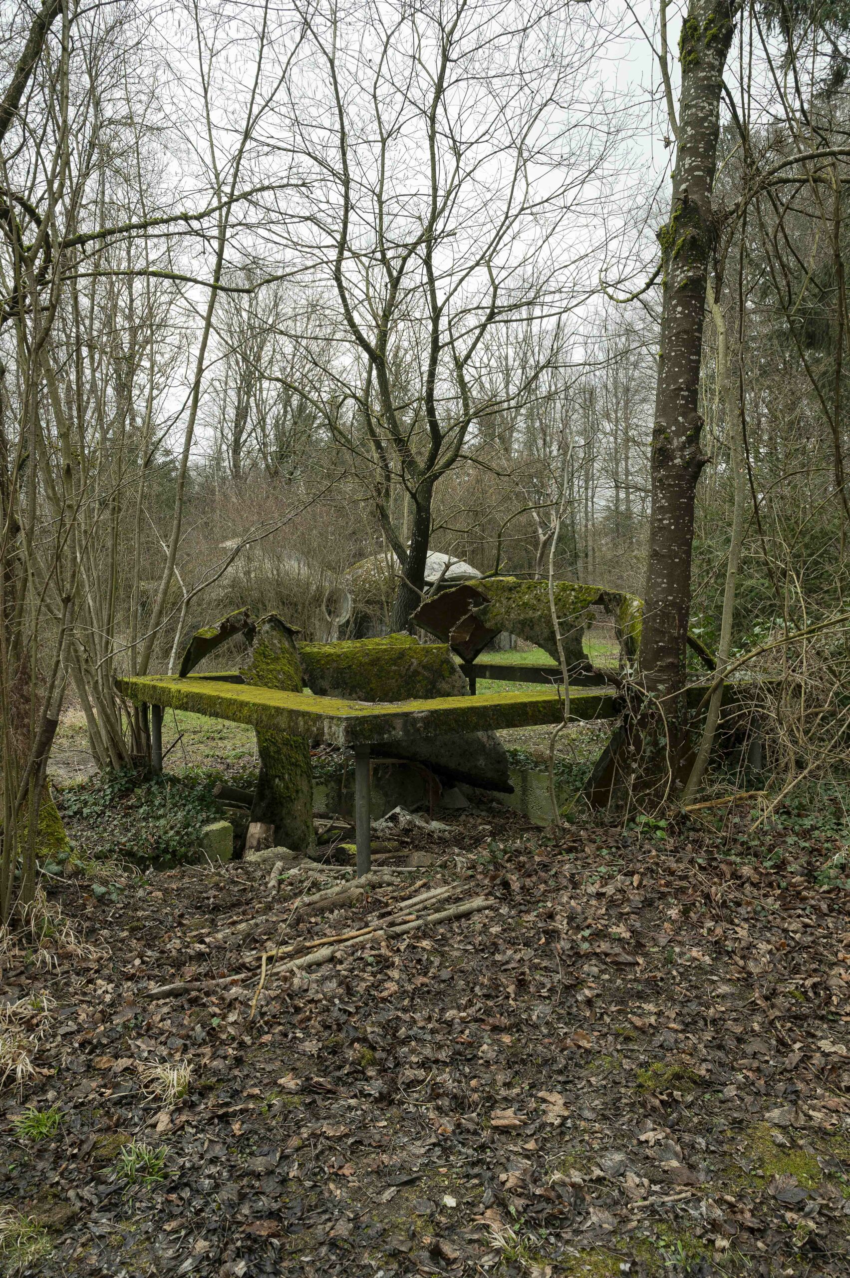
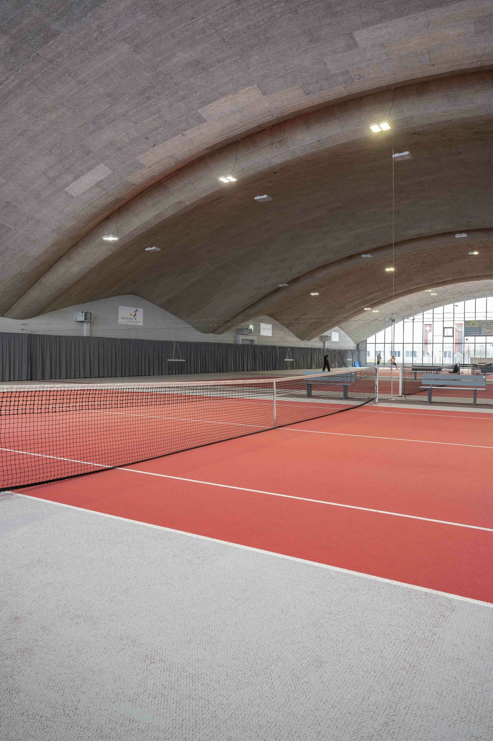
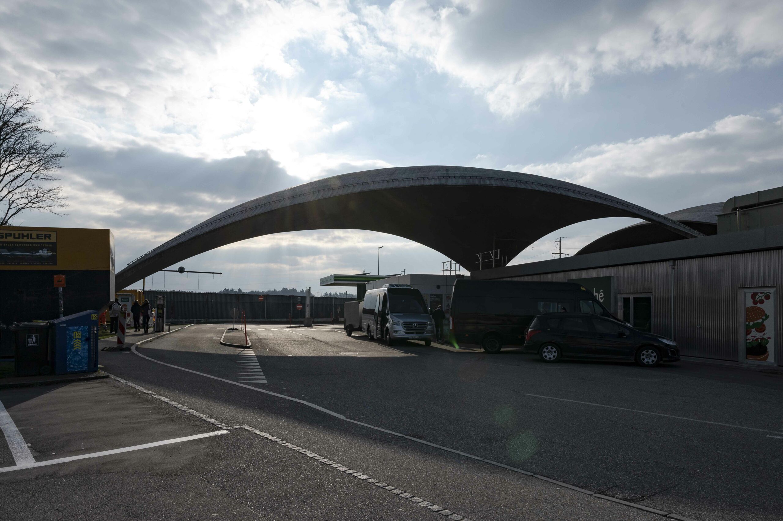
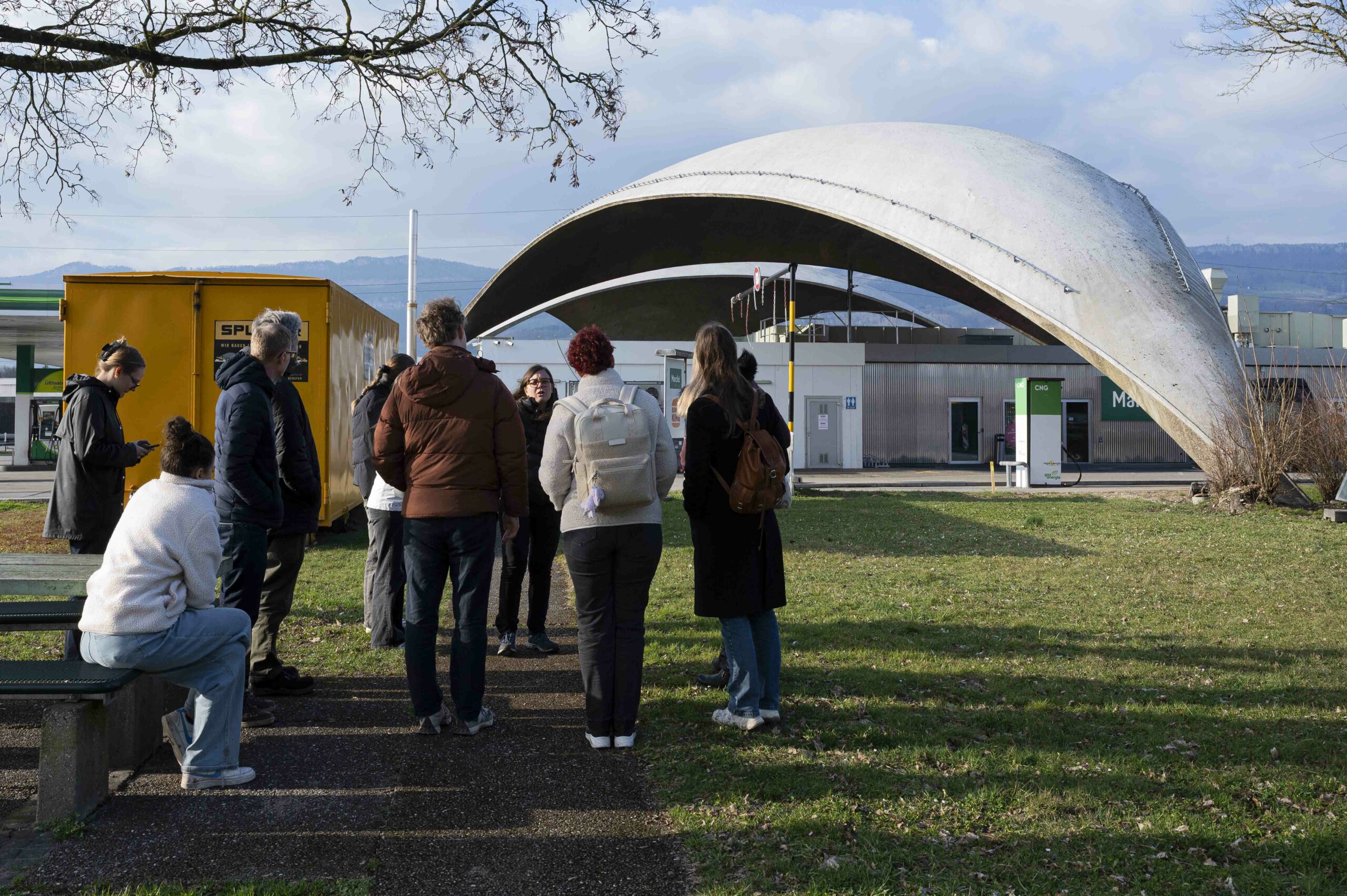
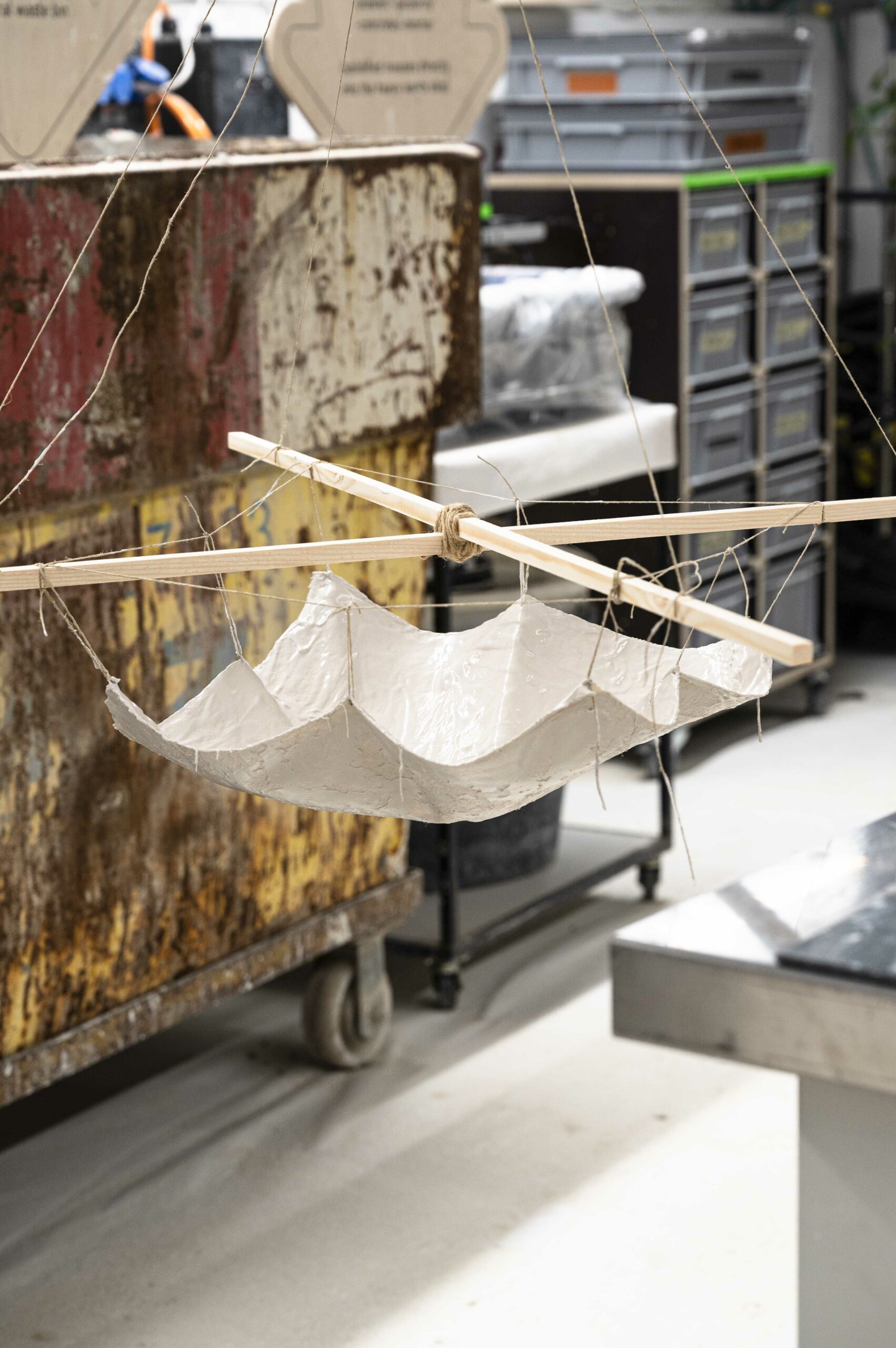
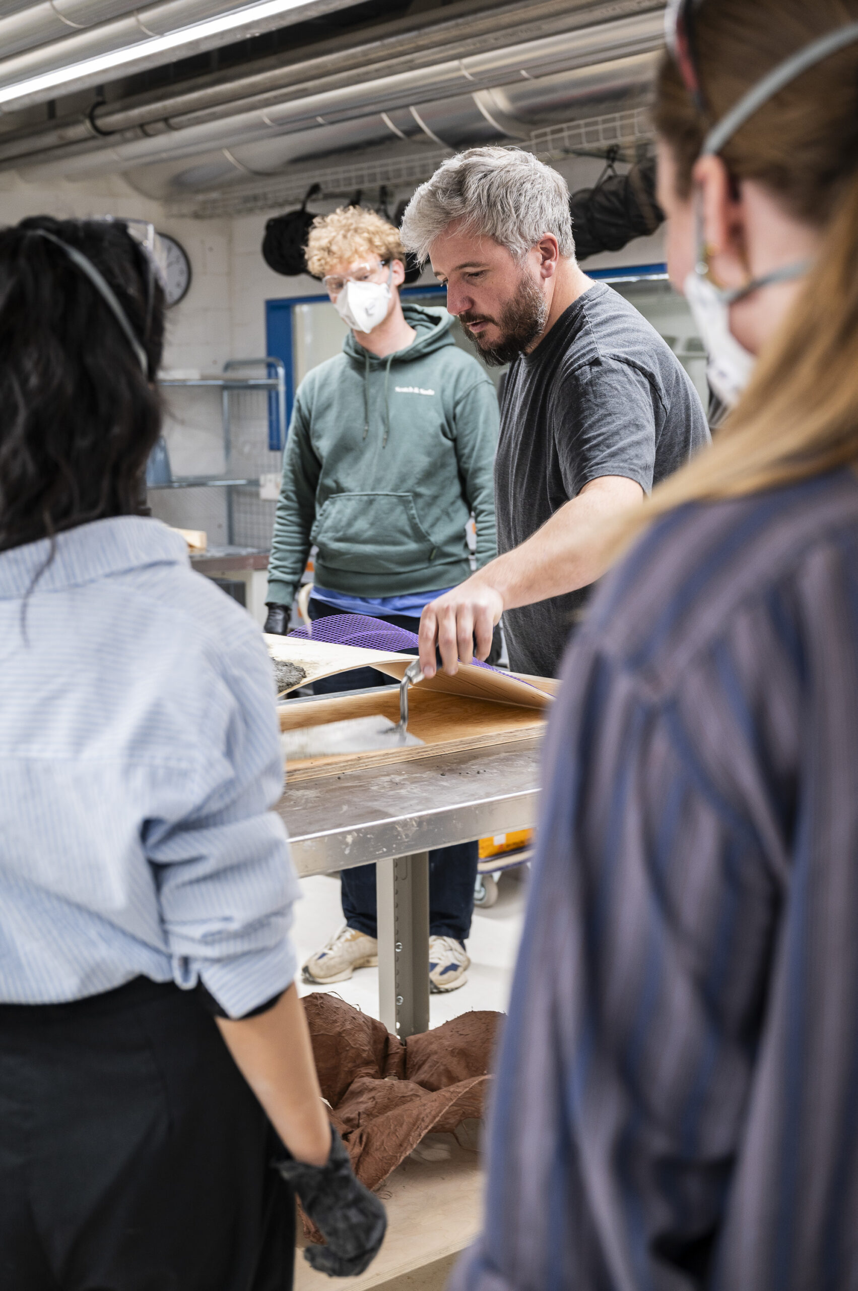
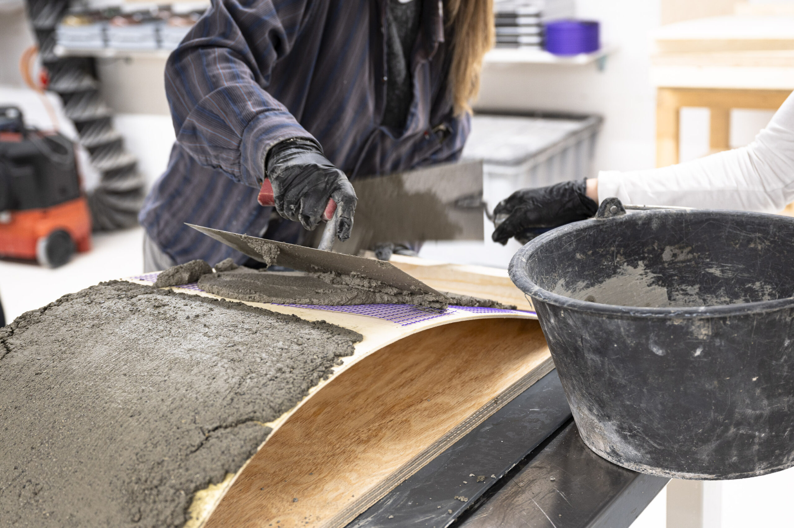
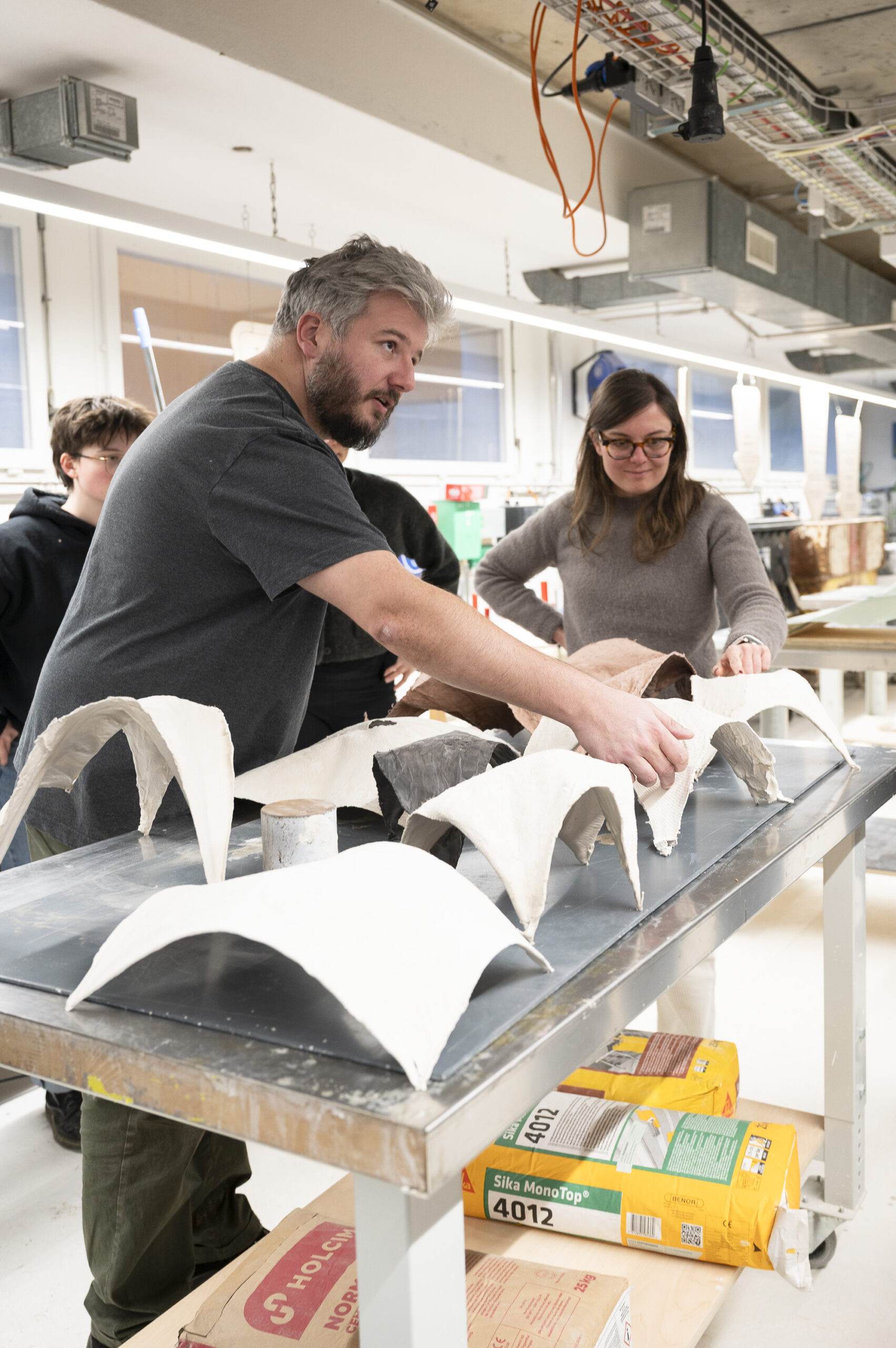
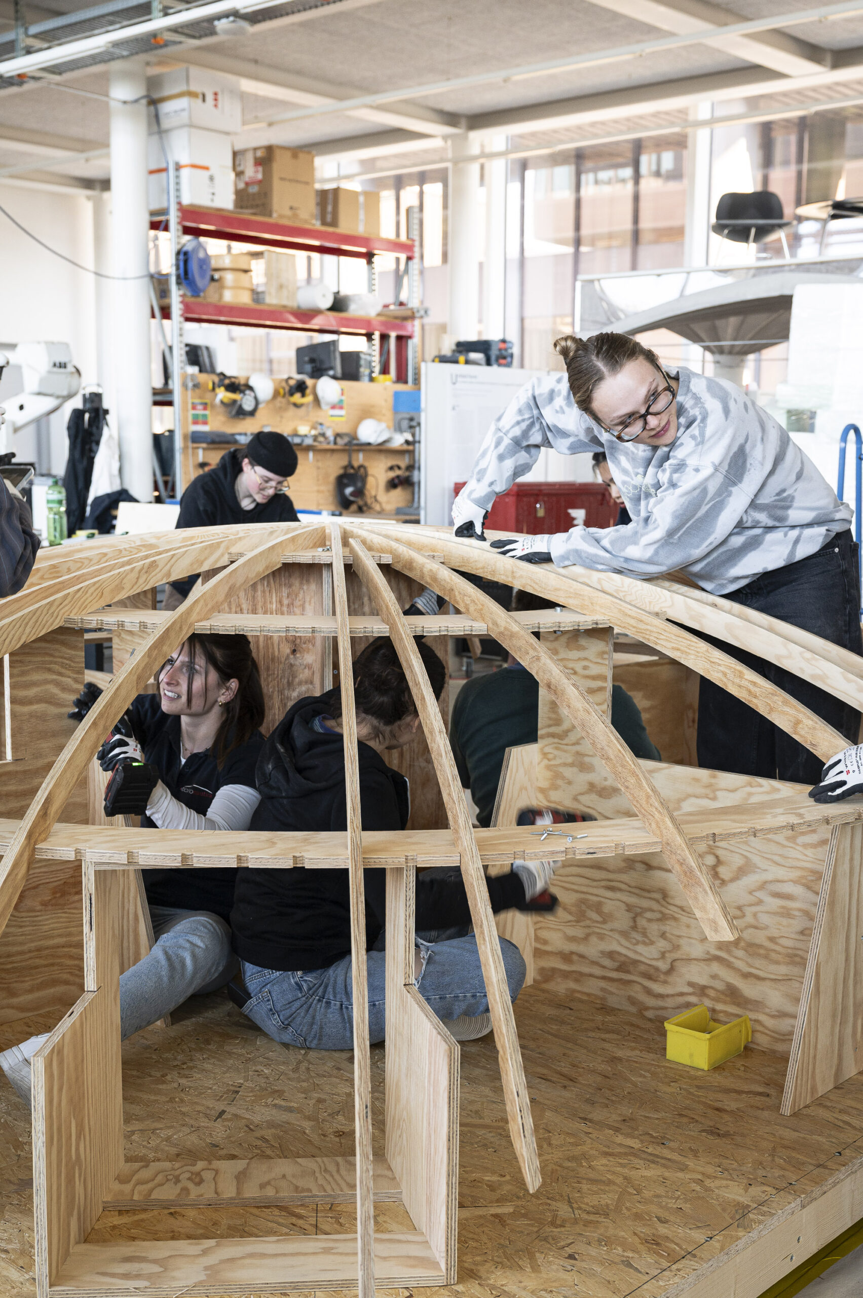
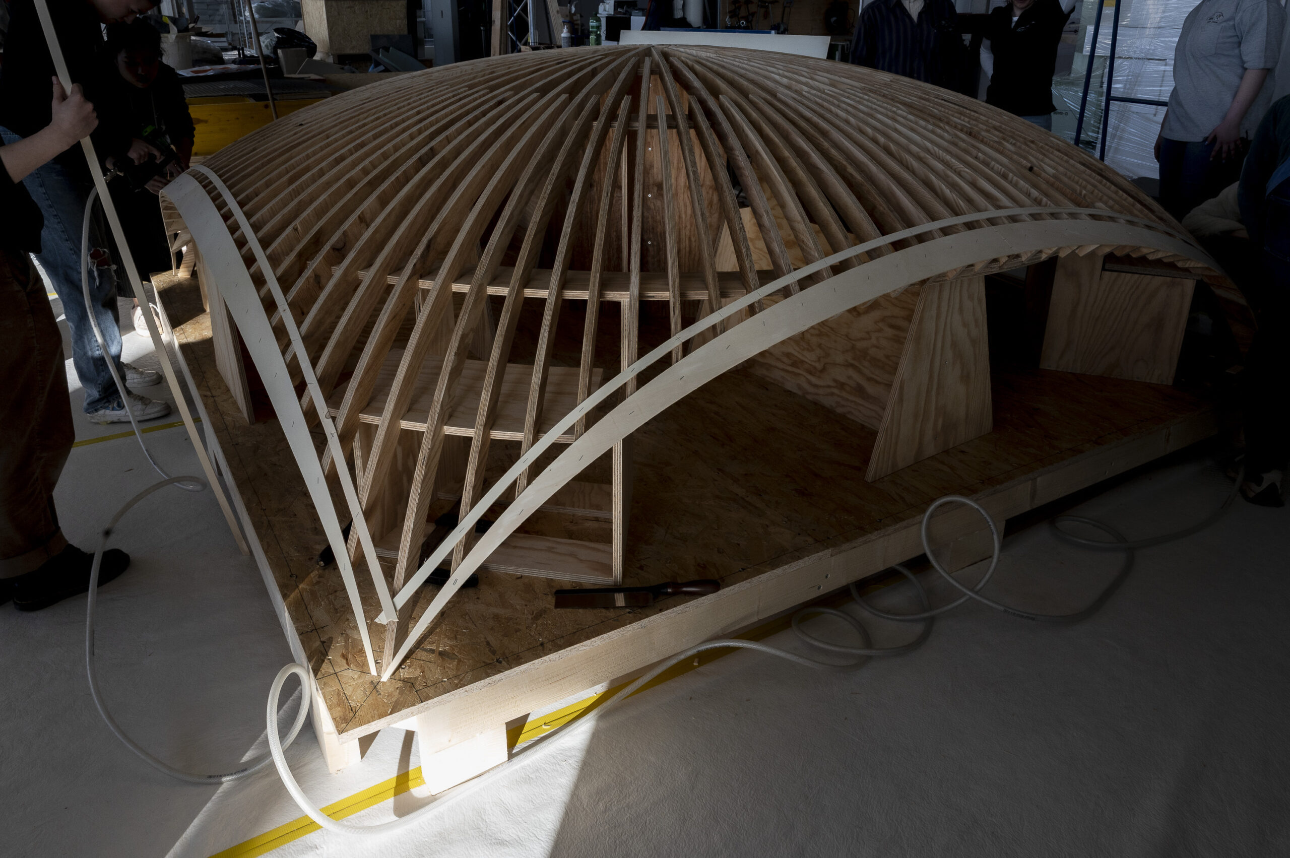
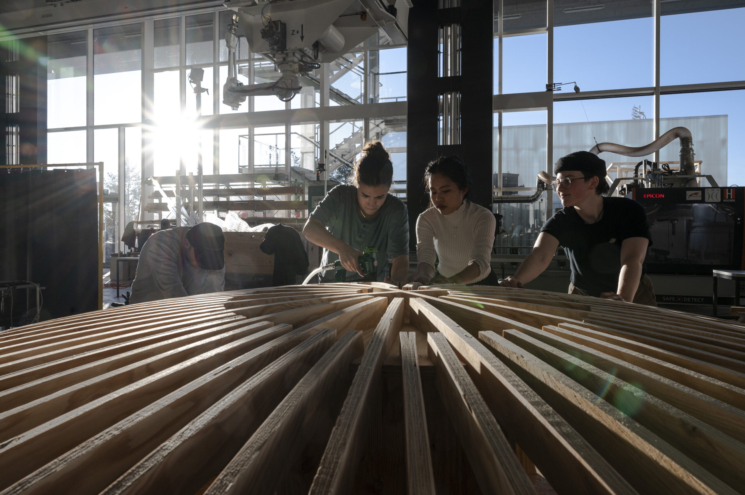
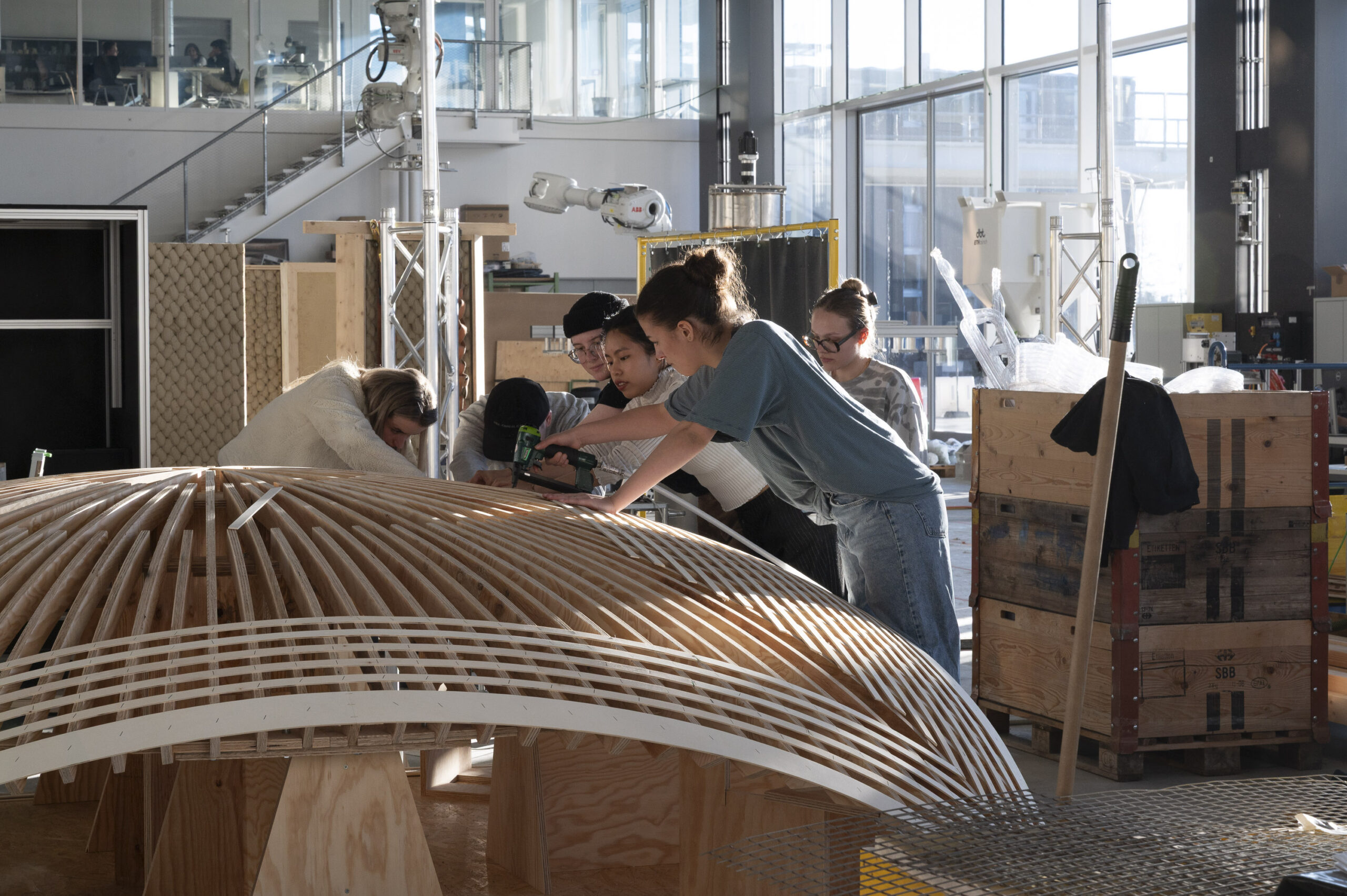
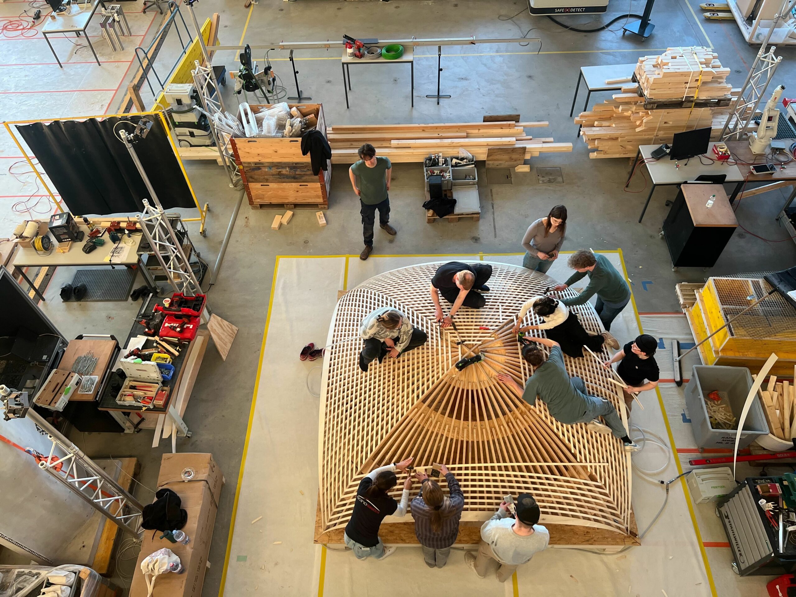
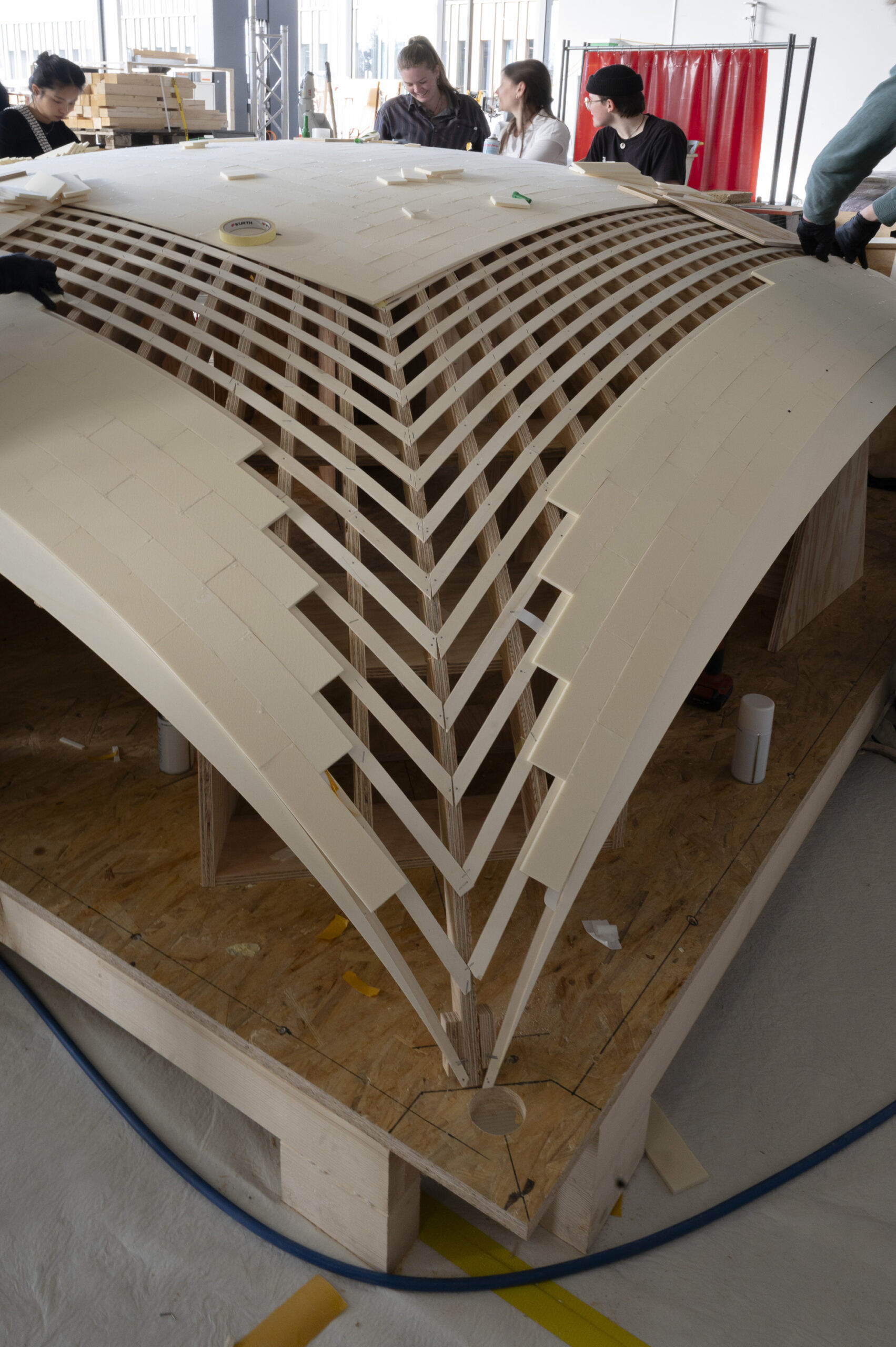
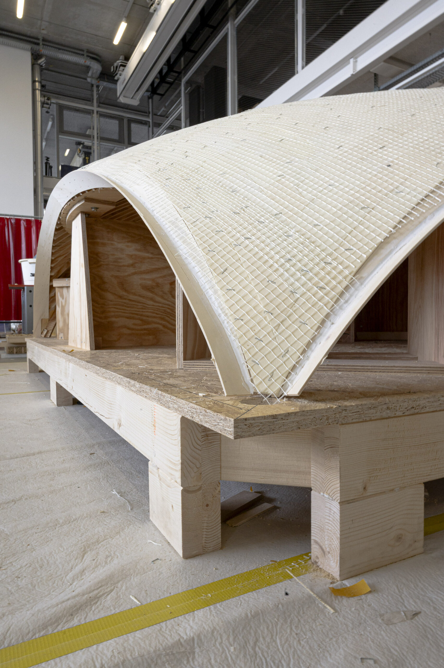
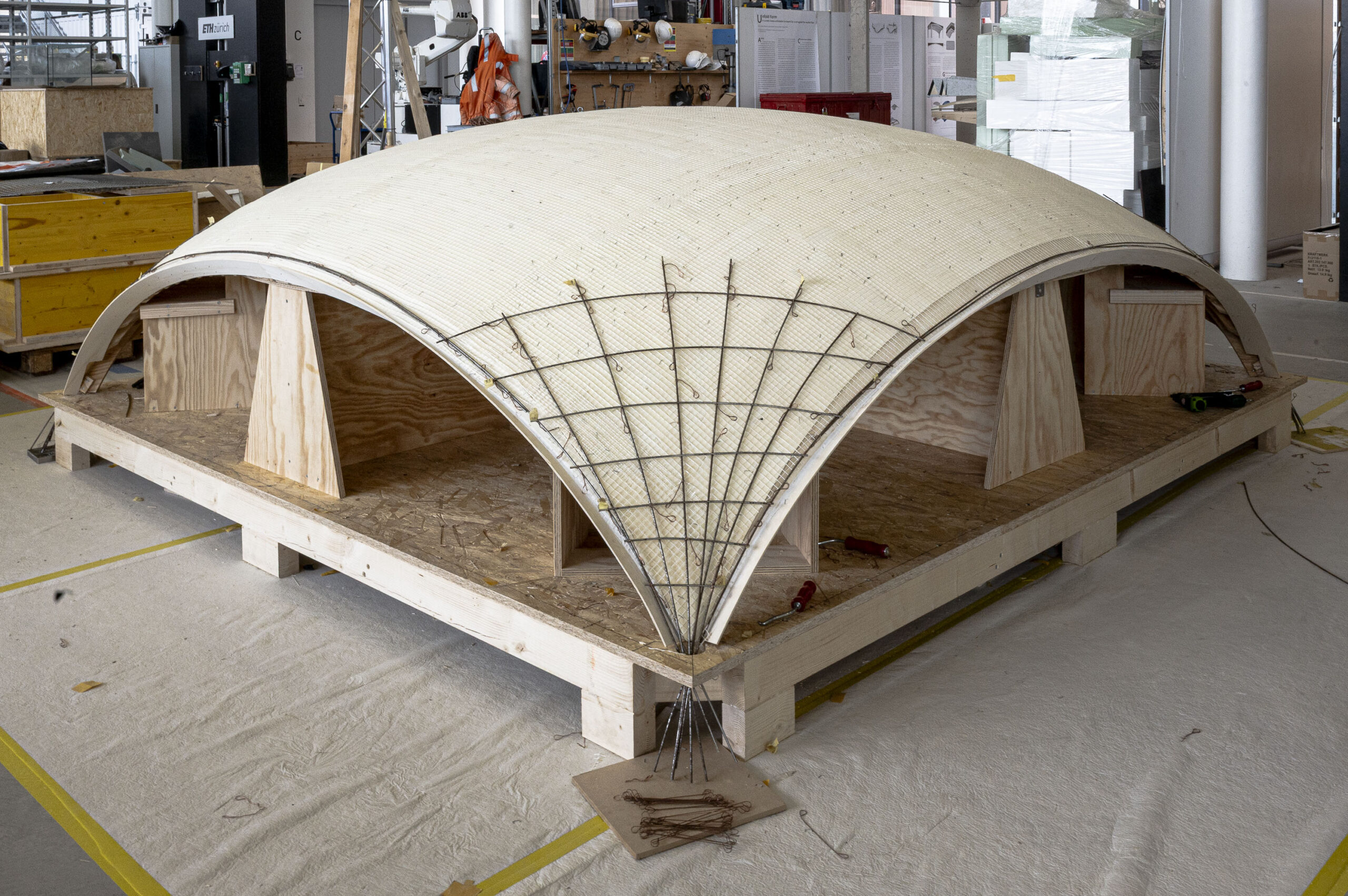
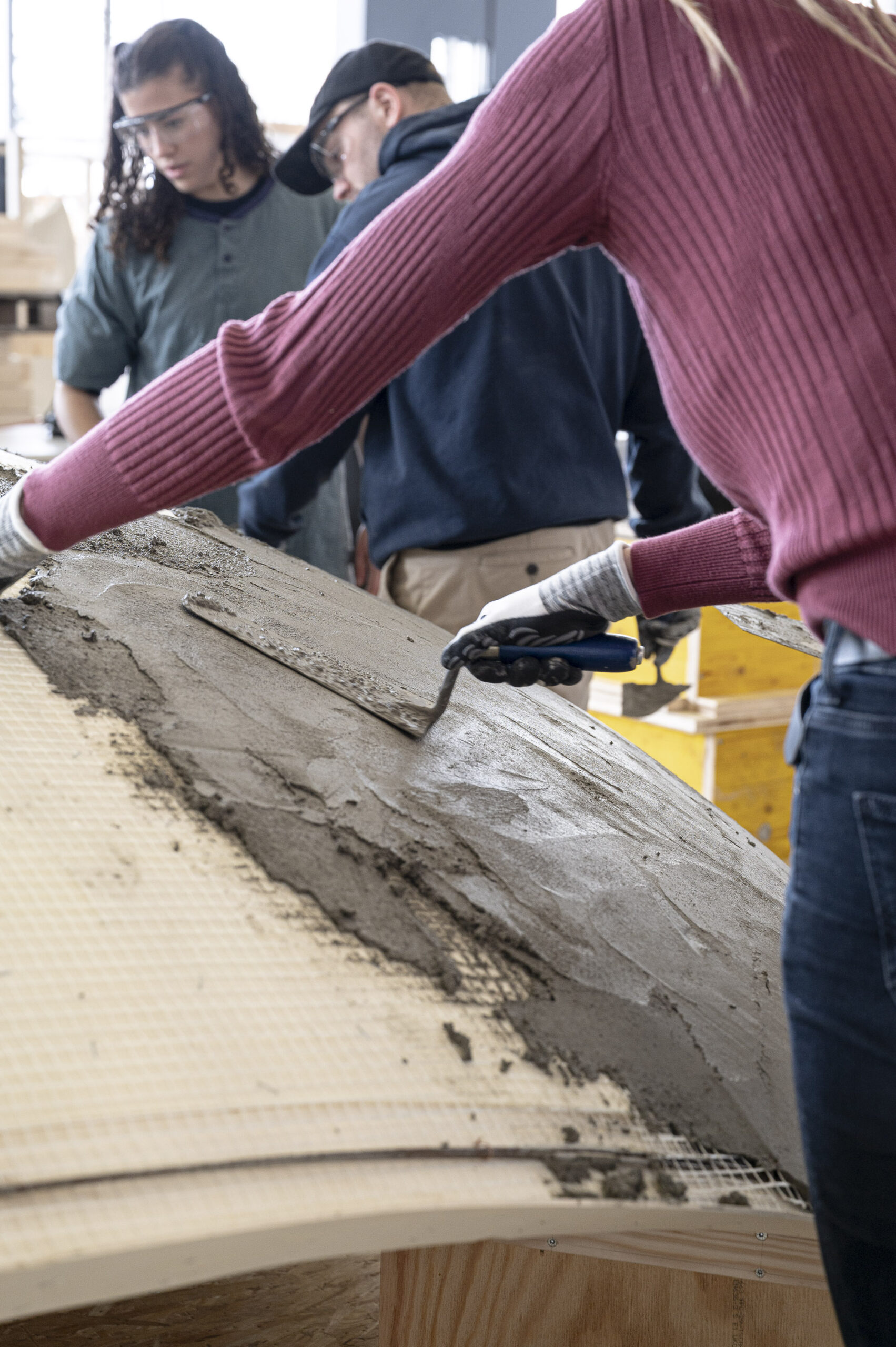
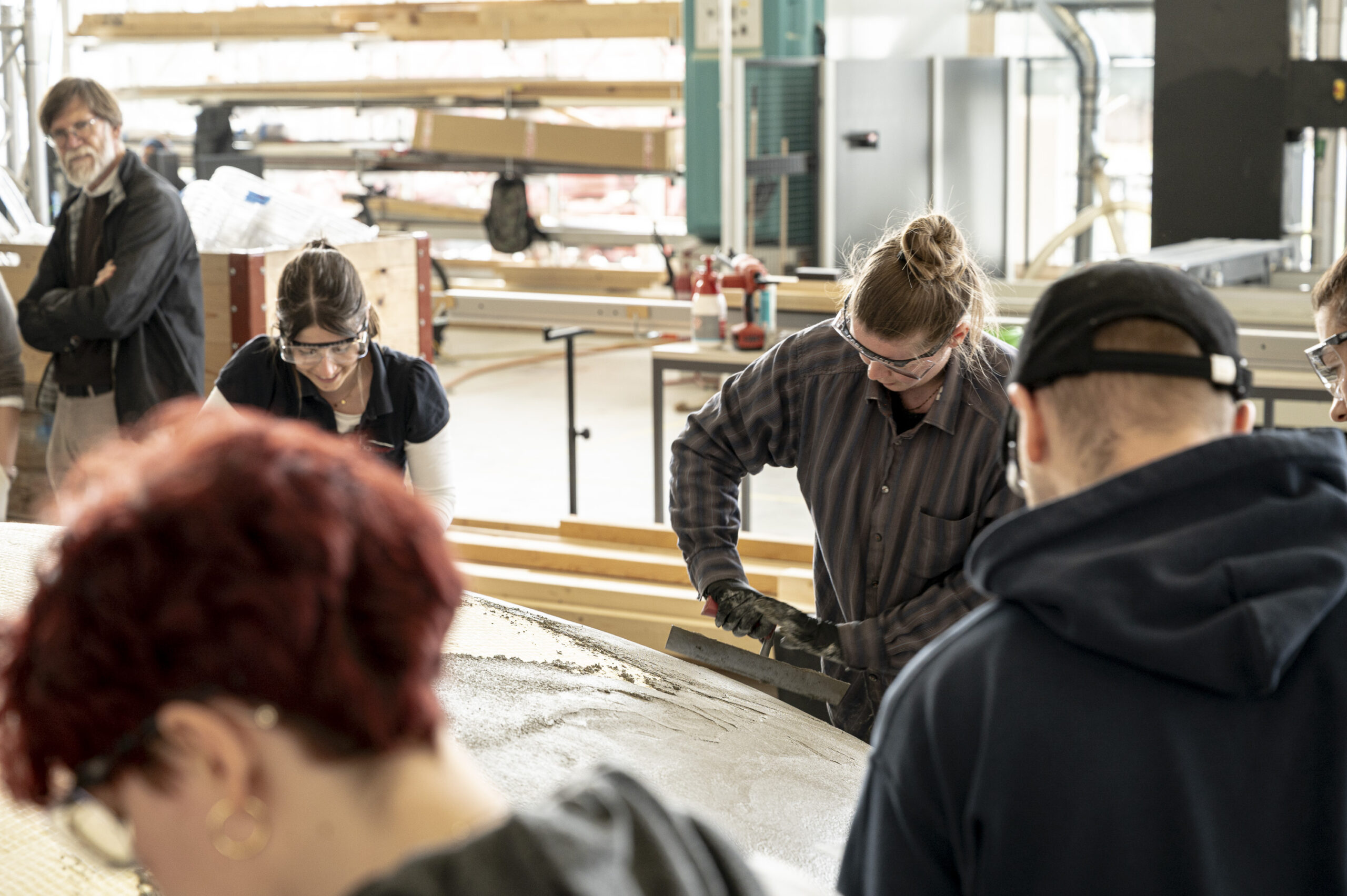
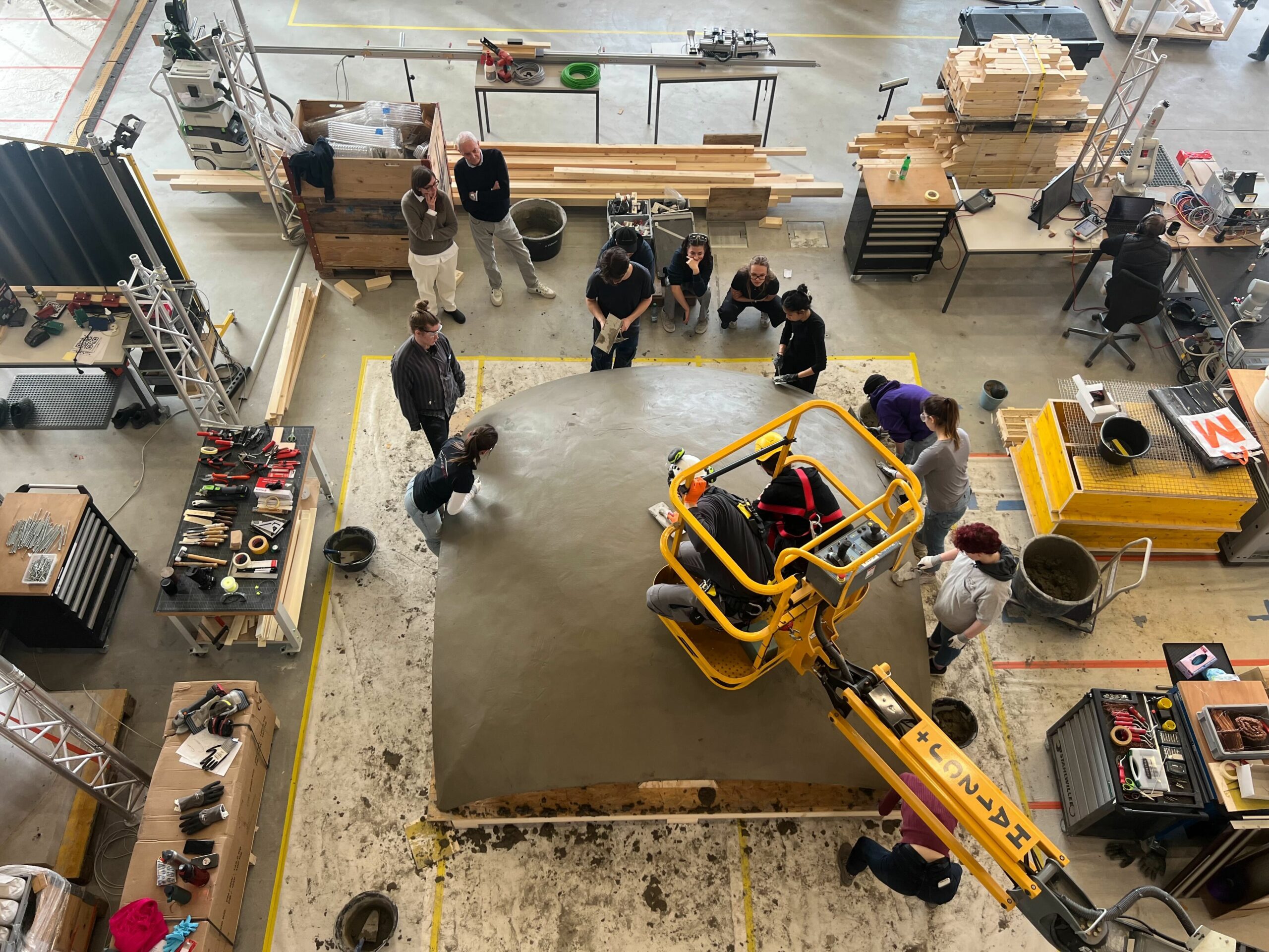
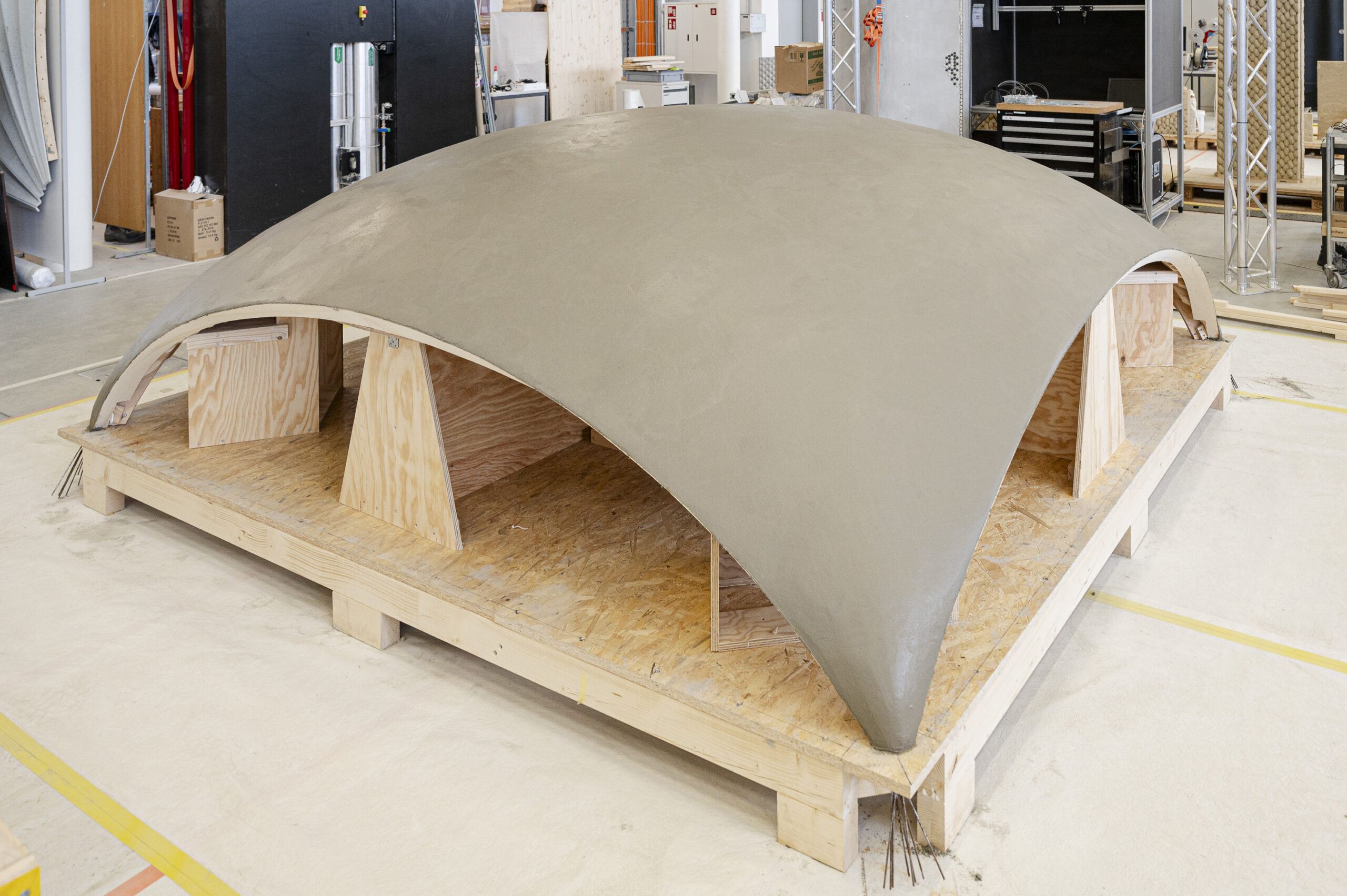
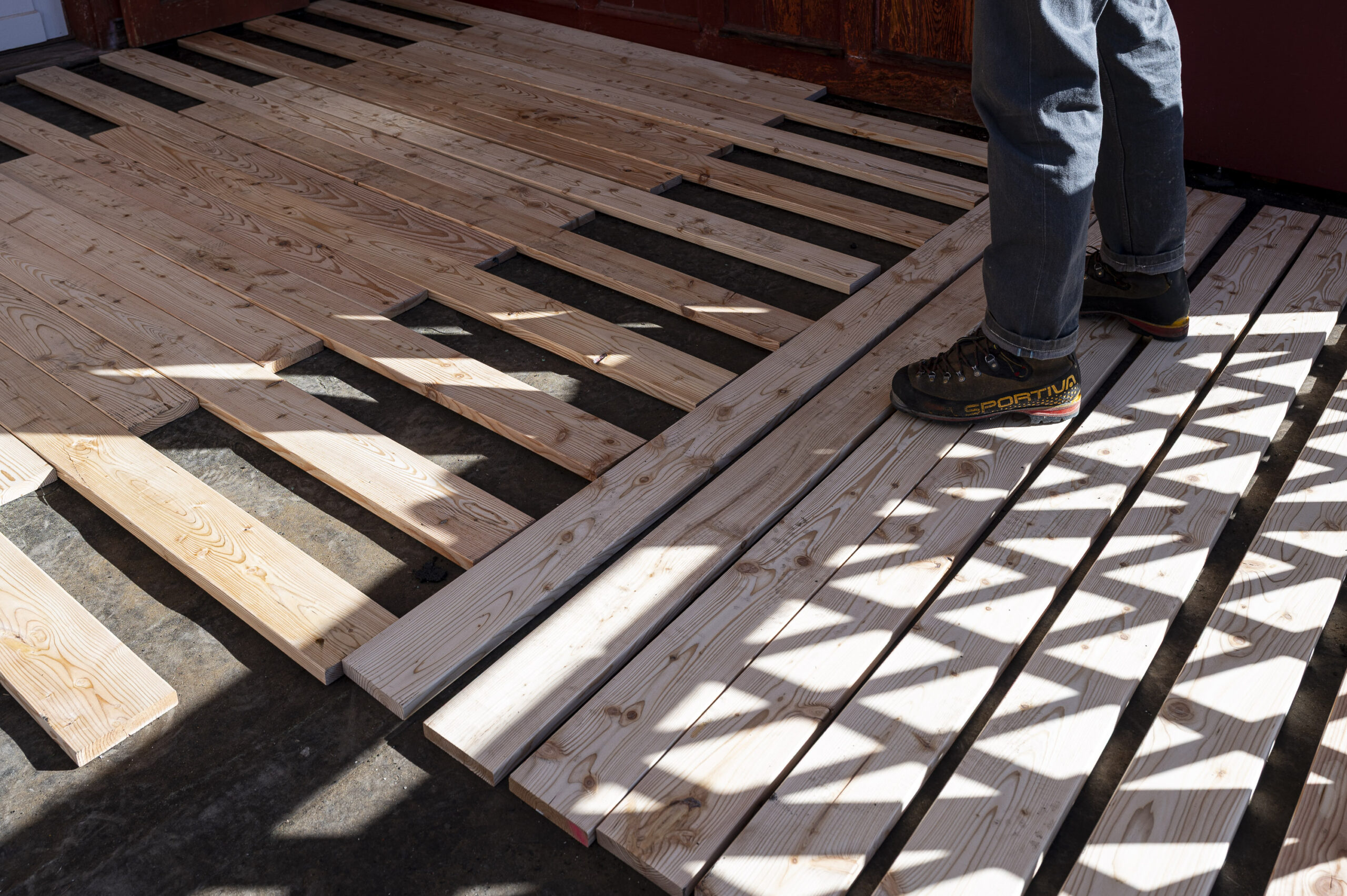
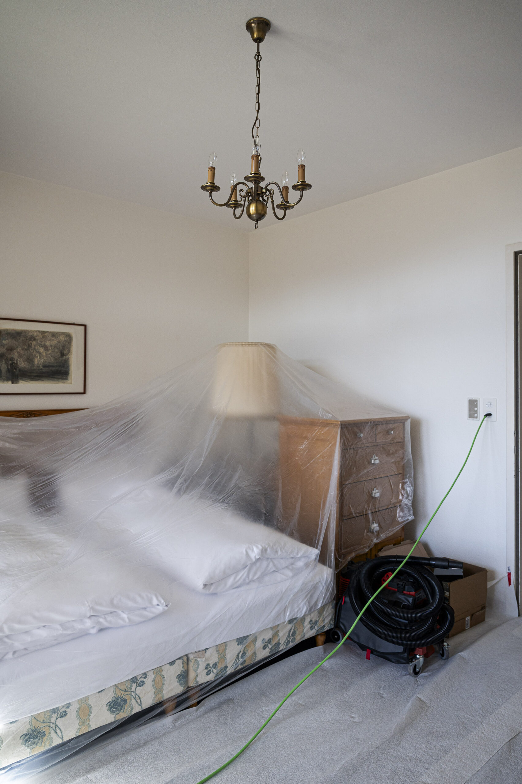
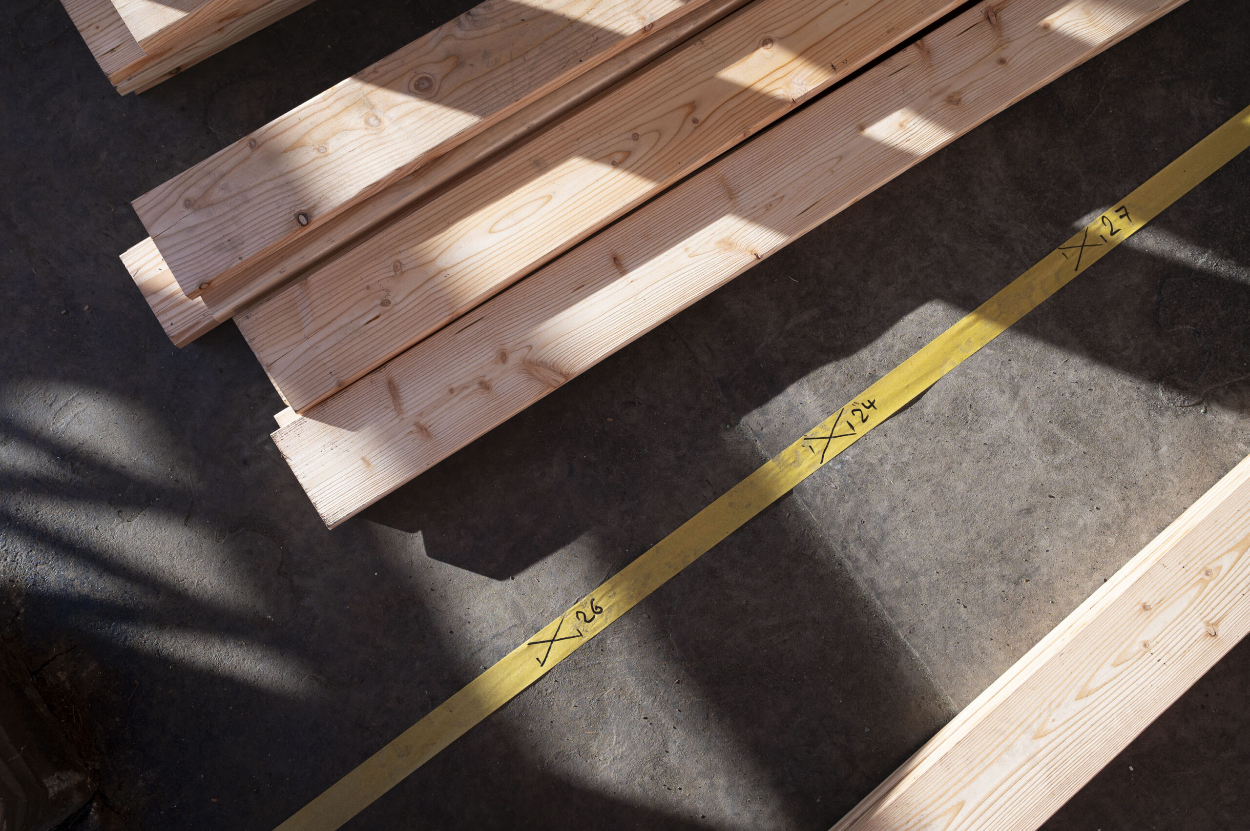
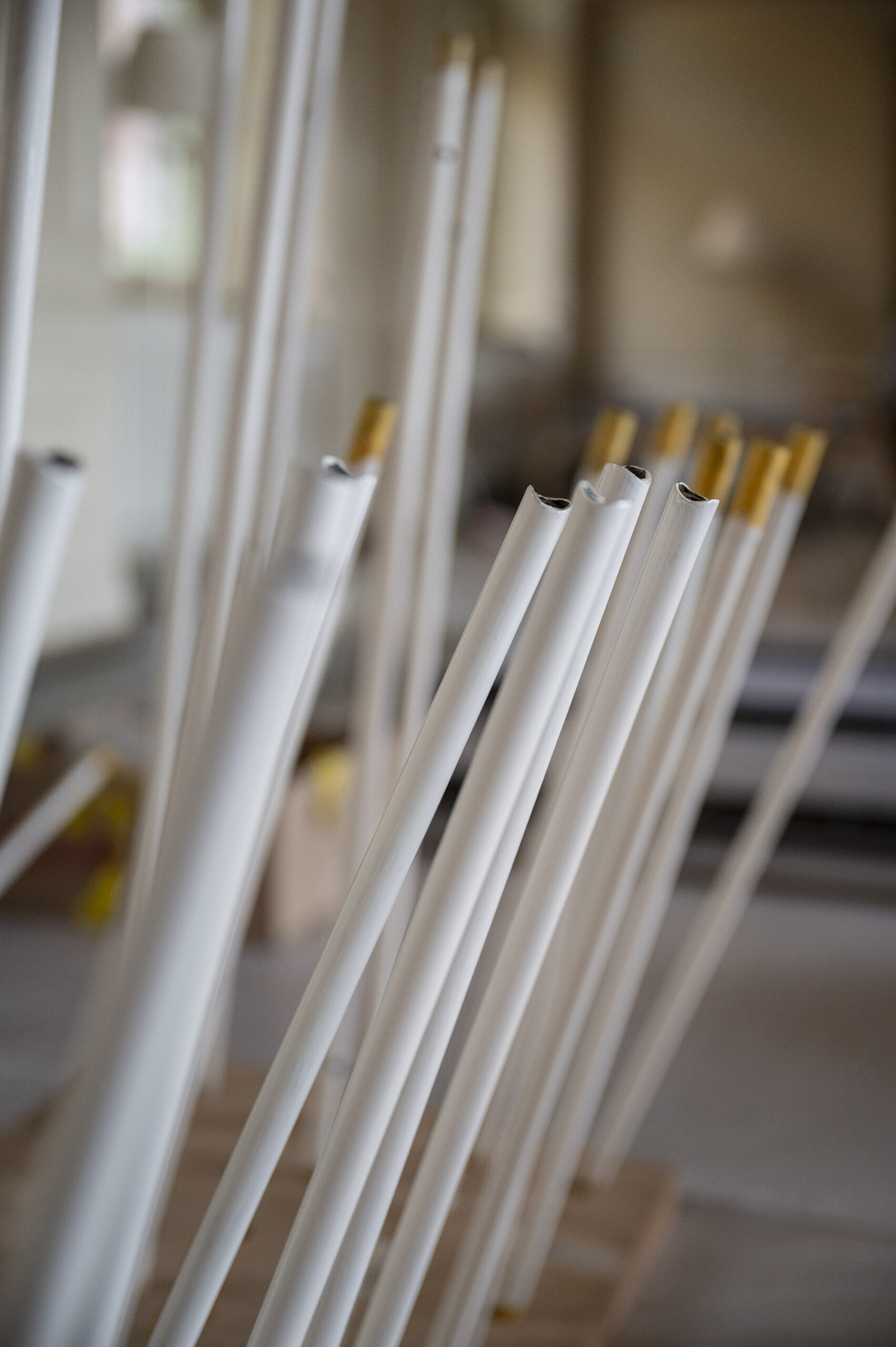
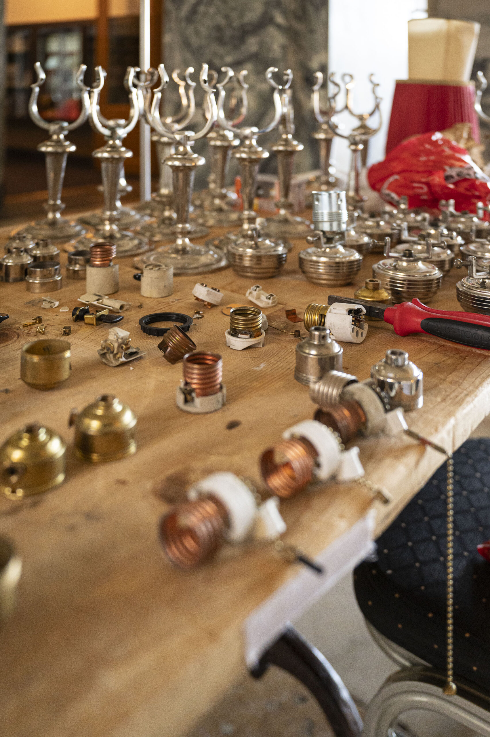
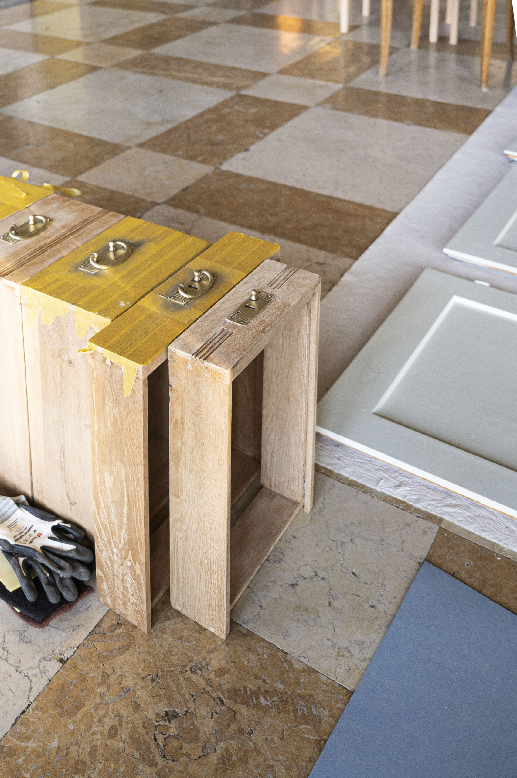
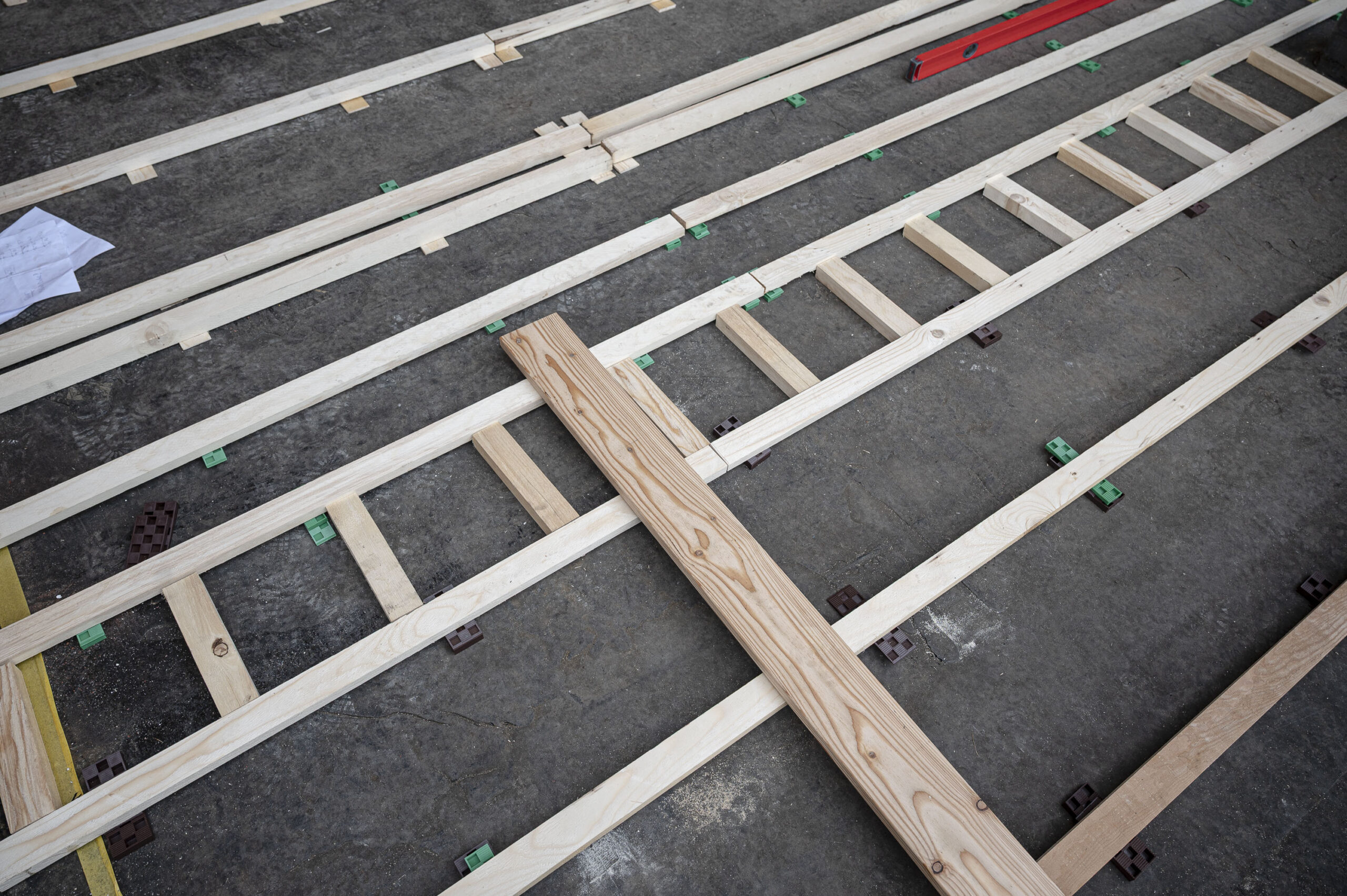
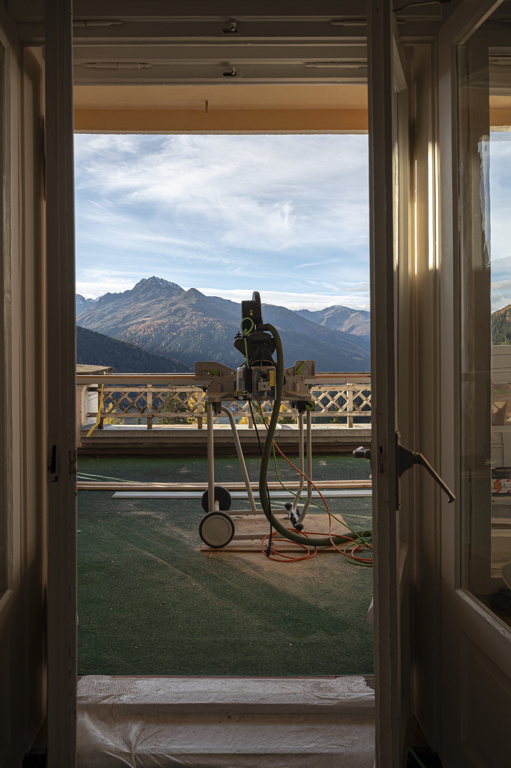
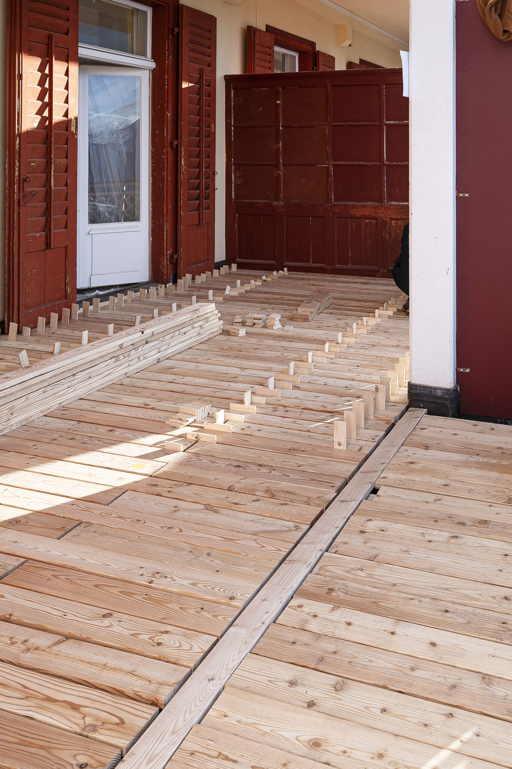
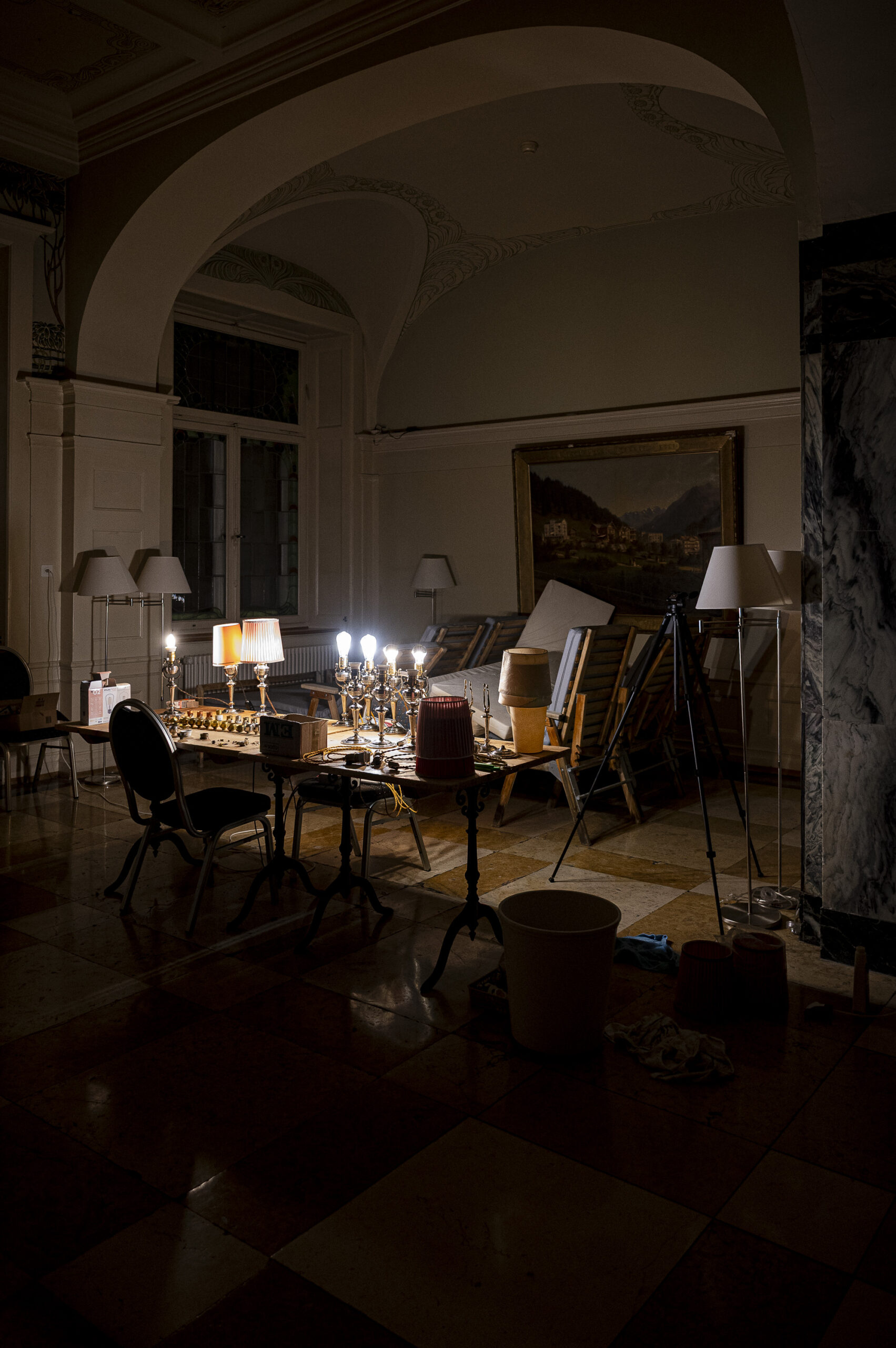
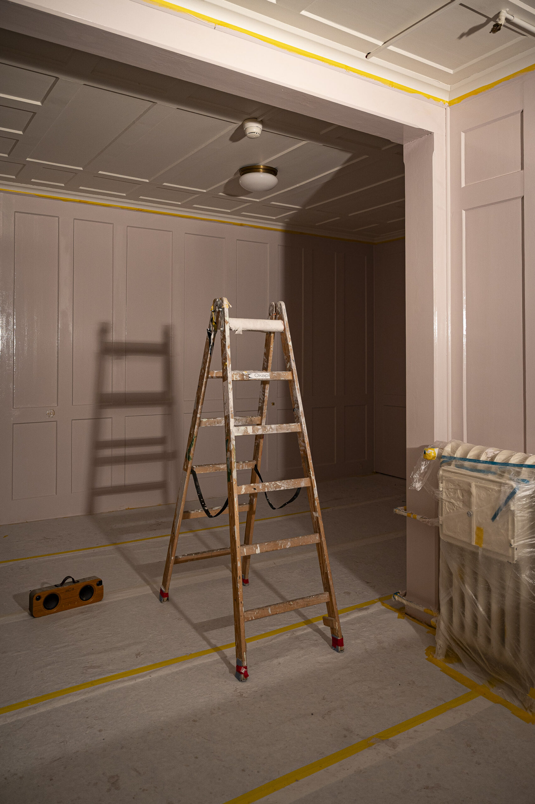
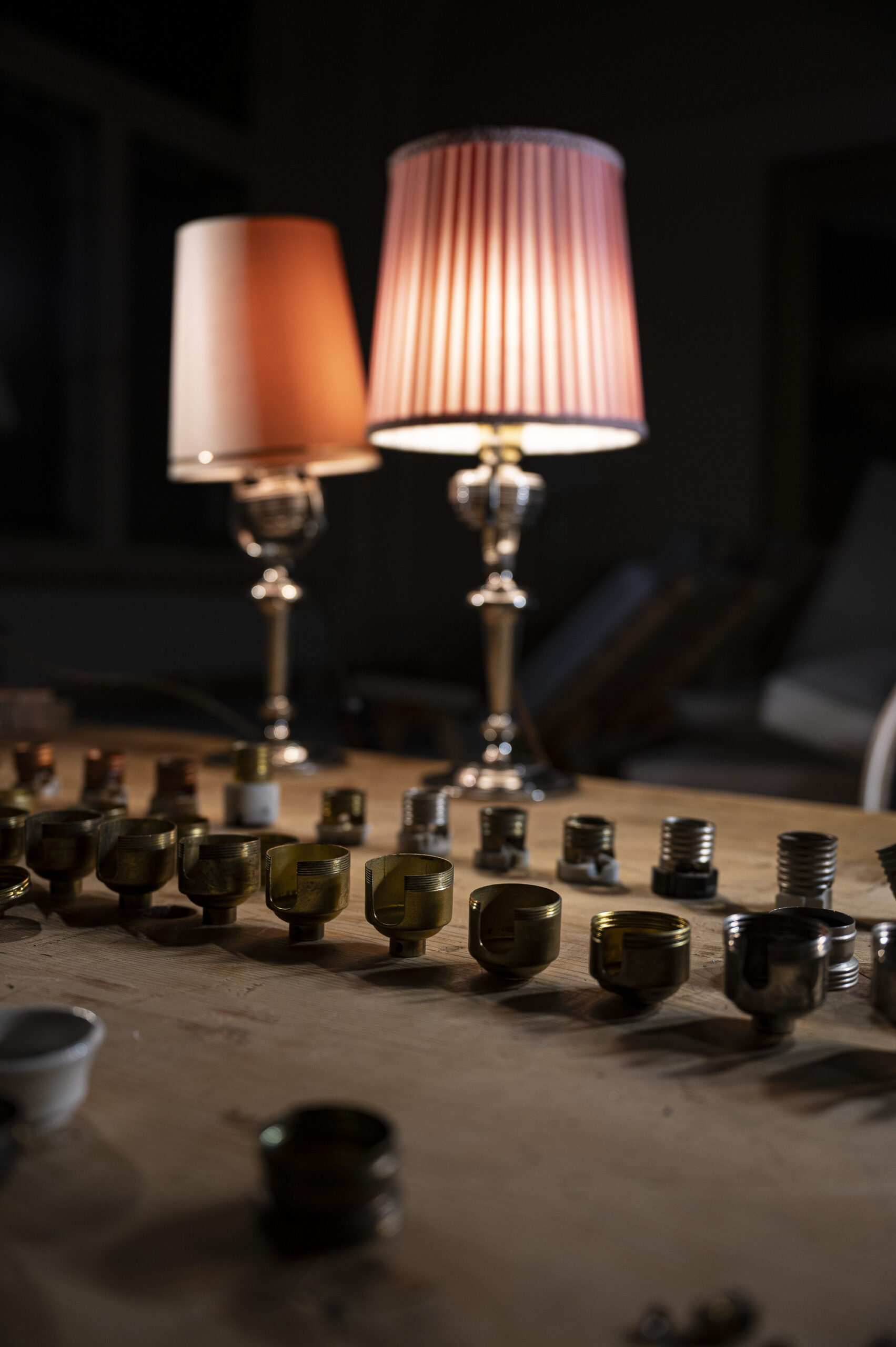
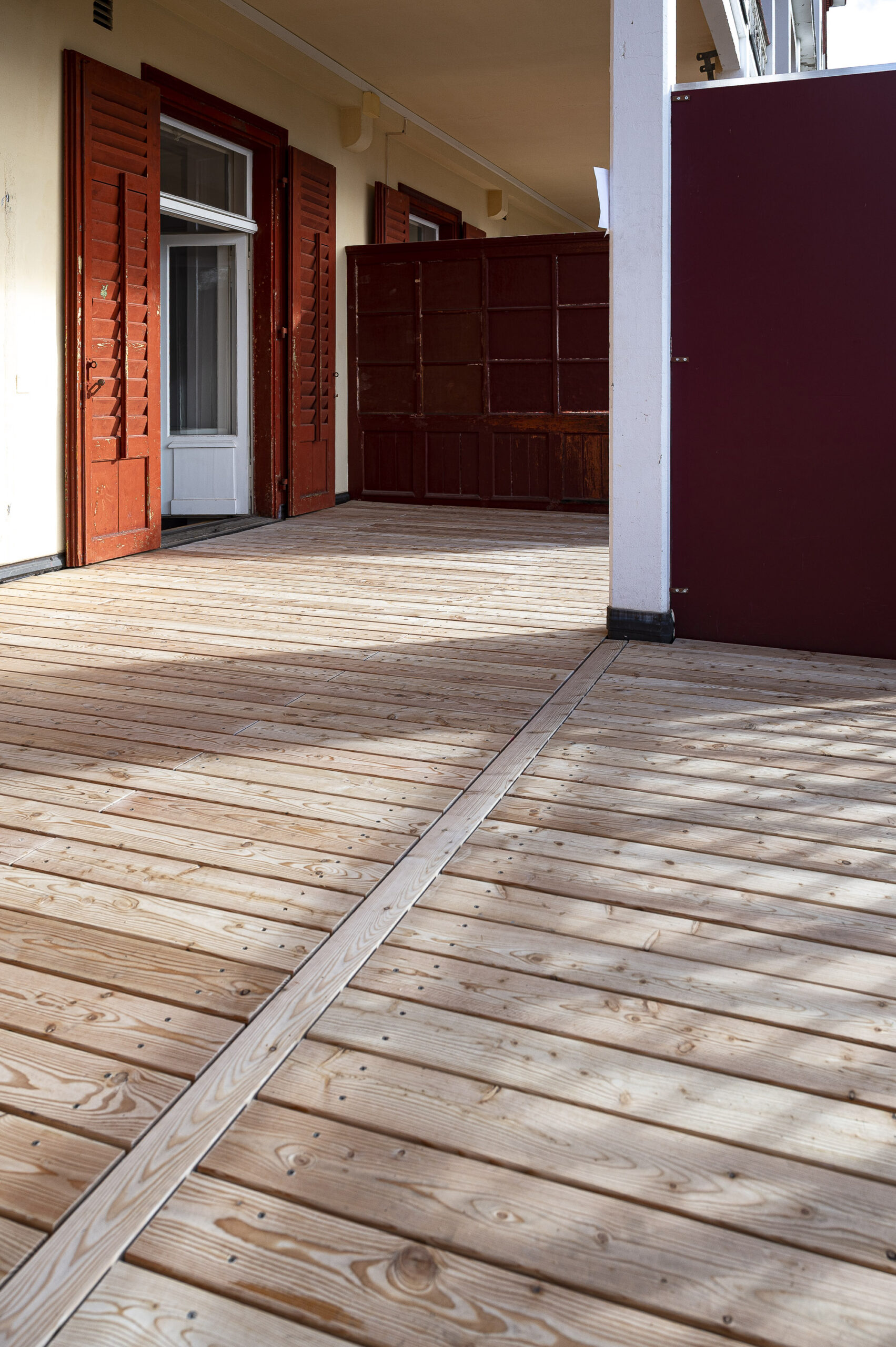
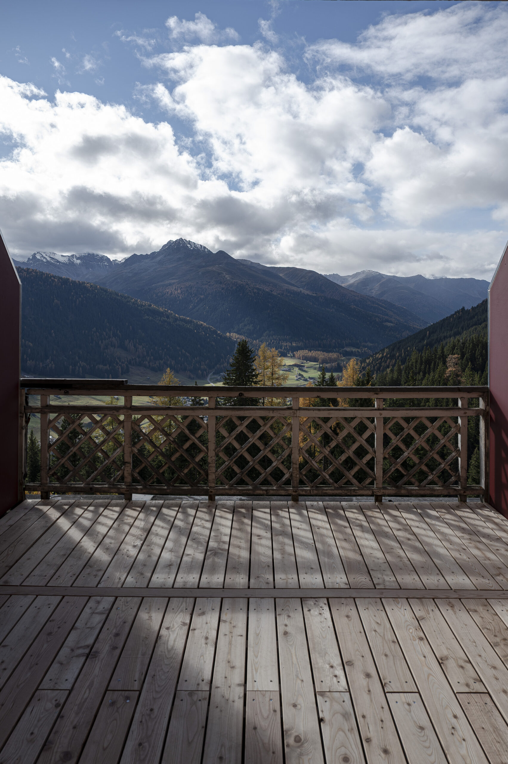
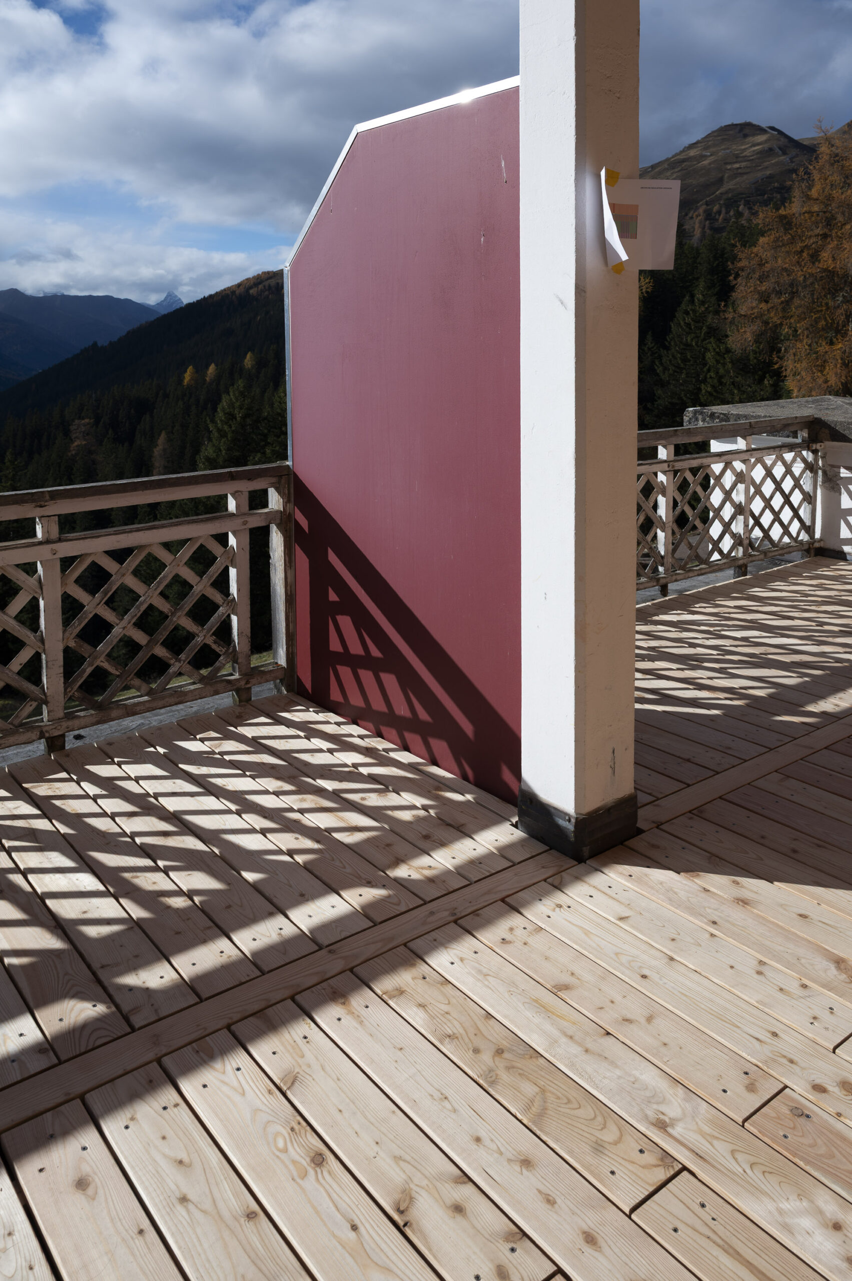
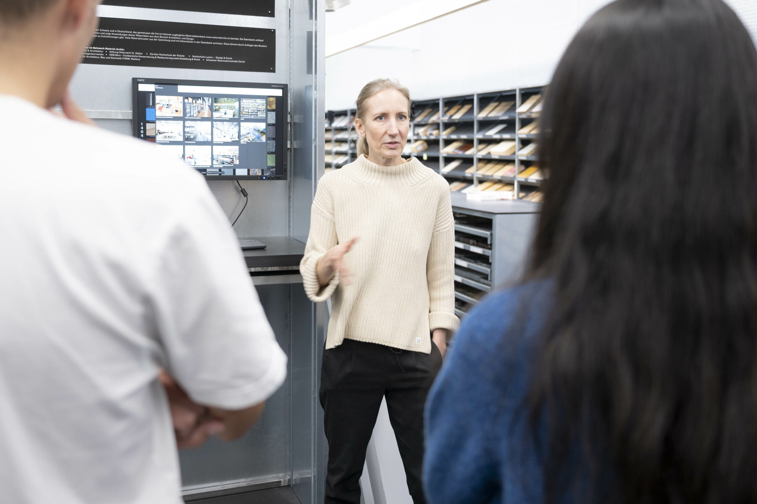
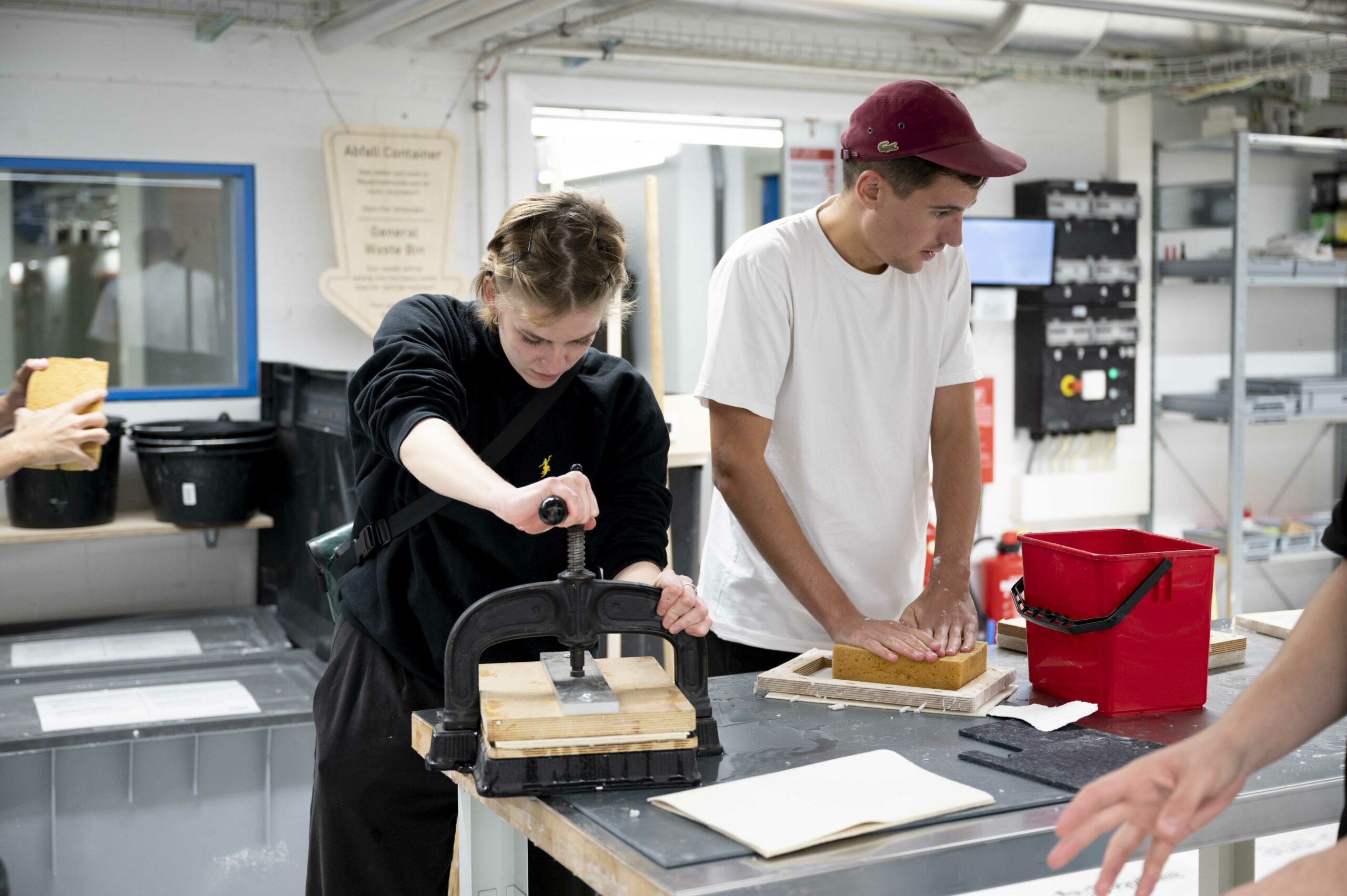
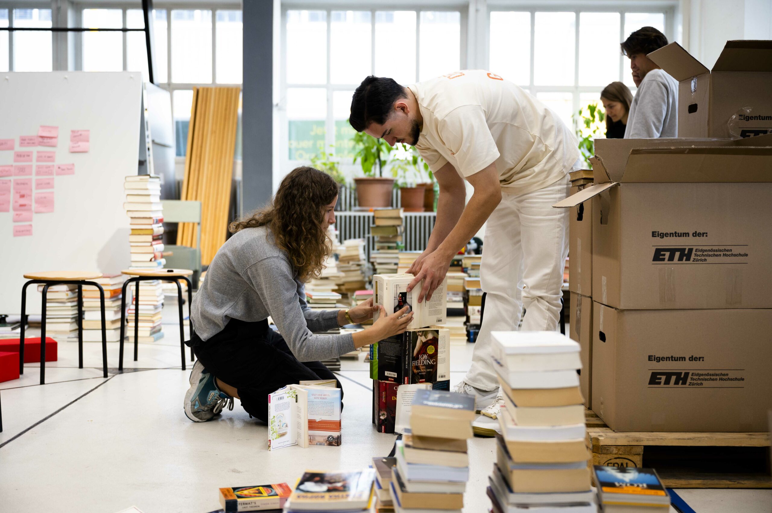
“The Innovedum Project “Maintanence and Repair ON SITE” integrates the teaching of preservation, construction, and sustainability with architectural design. The elective course “Repair: Keep in Place” is aligned with a design studio on building within the existing context and an on-site design-build seminar week, to offer a semester focusing on repair and maintenance in architecture.
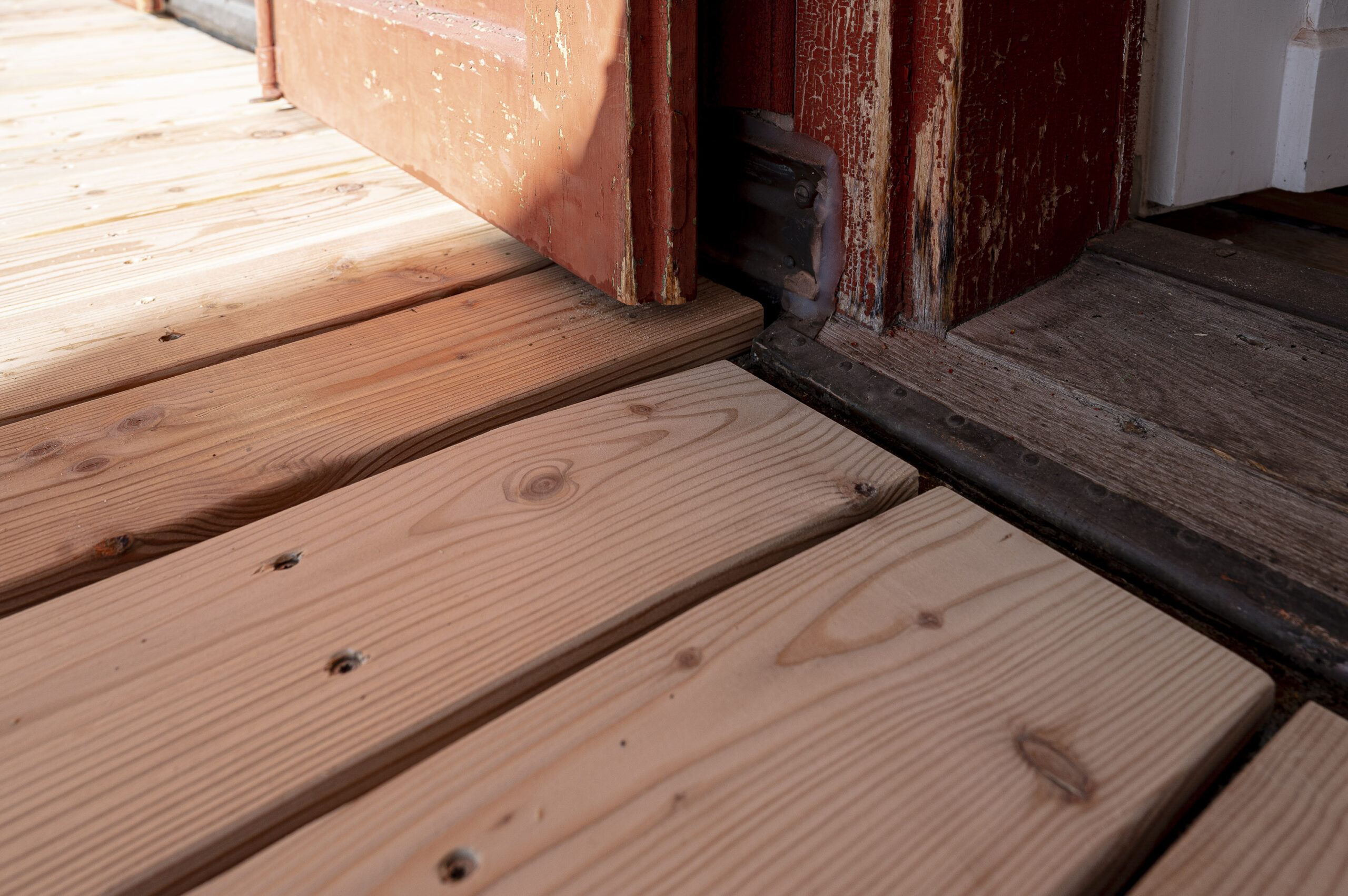
Difficult to maintain constructions and industrial manufacturing processes decrease the lifespan of objects not only in product design but also in architecture. Repairability is becoming less of a concern – replacement seems to be the norm. We need to rethink the way we build, starting already with the planning phase.
In this course, we combine traditional topics of preservation with concepts of repair to raise awareness for sustainable thinking and action. Students will learn both traditional and digital methods as well as the basic building and material criteria for repair. The objective is not only the hands-on repair within the built environment but especially to learn about the concepts of heritage preservation.
For the current semester, the repair concepts from the elective course are being carried out on site as part of the Design–Build seminar week at the Schatzalp in Davos.”
A strong safety culture minimizes risks and contributes to the overall success and sustainability of workshop operations. Raplab has distilled four overarching principles that capture our safety culture, which is applied in addition to the many operational rules that need to be followed in the different workshops for individual machines or materials.
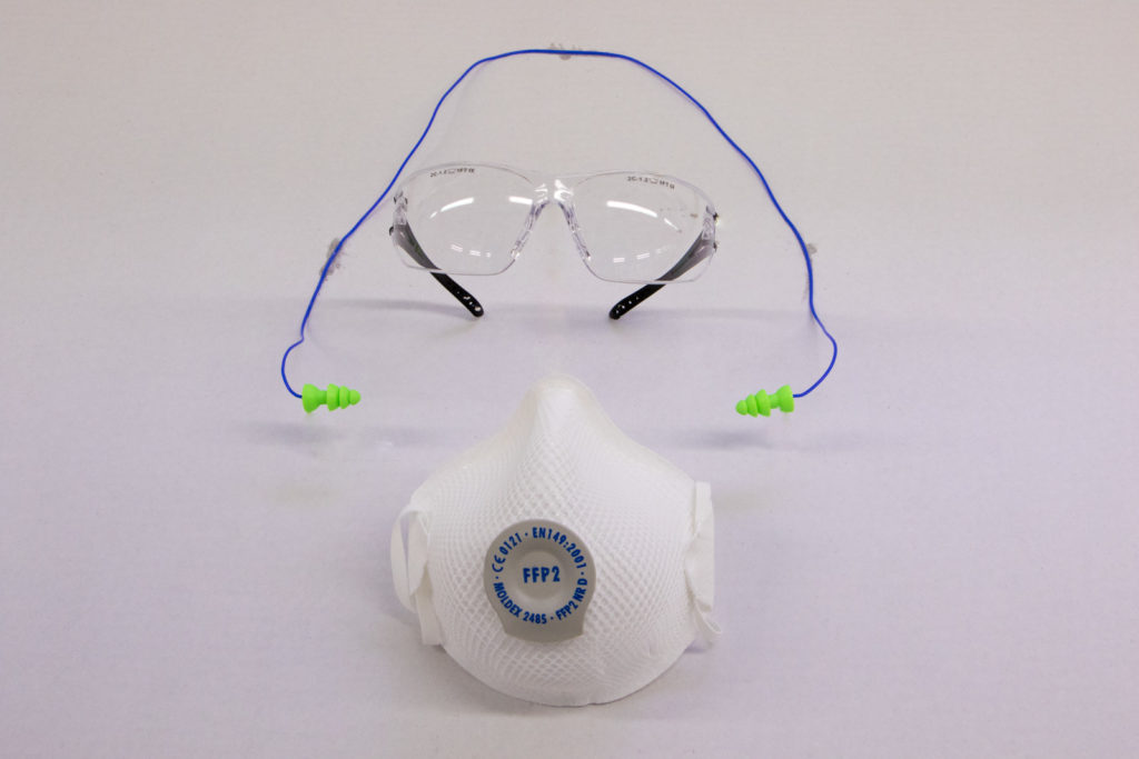
1. PREPARE
Preparedness is a critical factor in preventing injuries and ensuring work efficiency. Having a mental map that involves knowledge of tools, materials, and safety gear necessary to complete a task helps to avoid haste and, therefore, the chance of mistakes.
2. ACT RESPONSABLY
Acknowledging our roles and responsibilities towards ourselves and others is vital to an open, do-it-yourself workshop environment. Being aware of the protocols and rules for each workshop and ensuring that those rules are followed is second nature to us. In case of doubt, we ask a staff member before proceeding.
3. BE RESPECFUL
The Raplab is a place of respect and acceptance where students and staff exchange openly. Respect and acceptance go both ways to ensure the well-being of all parties involved. We strictly follow the Code of Conduct laid out by the D-ARCH community. We train ourselves to be aware of others’ needs, especially during times of high pressure and when the workshop is crowded.
4. CARE
We collectively strive to reduce our environmental impact by caring for tools, machines, our shared spaces, and the materials we use. We reuse material or use material in a way that minimizes waste. We use tools and machines for their intended purposes and report damaged tools. We use the rooms and infrastructure in a way that does not impede others from working.
If your job has small parts, it’s likely they will fall through the grid. This isn’t a problem as the grid can easily be removed to access the bottom tray.
Ensure the nozzle is towards the back of the machine
Lower the bed at least 5cm
Pull the red access panel towards you
Then simply lift up the front side of the grid without allowing it to twist
Remove your parts
Place the grid back making sure it is correctly seated with the locator pins
Put the red access panel back into position
Laser Engraving
There are 2 types of engrave options:
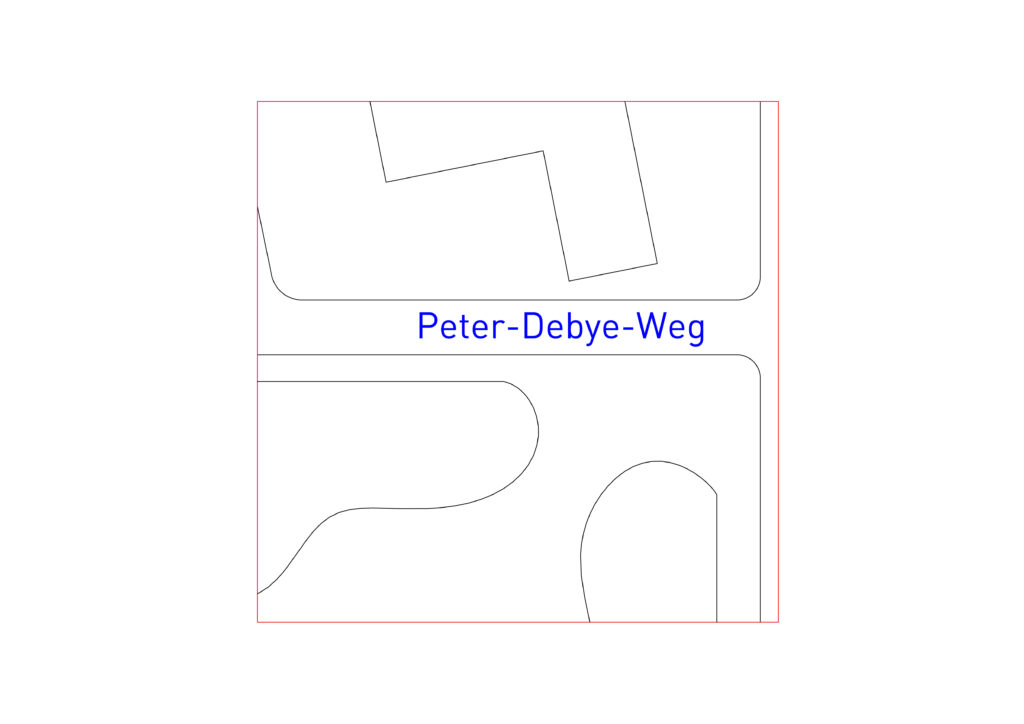
Raster engraving for engraved area (blue) and vector engraving for engraved lines (black). It is important to understand the difference to get the desired outcome and knowing which type to use when can also save a lot of time.
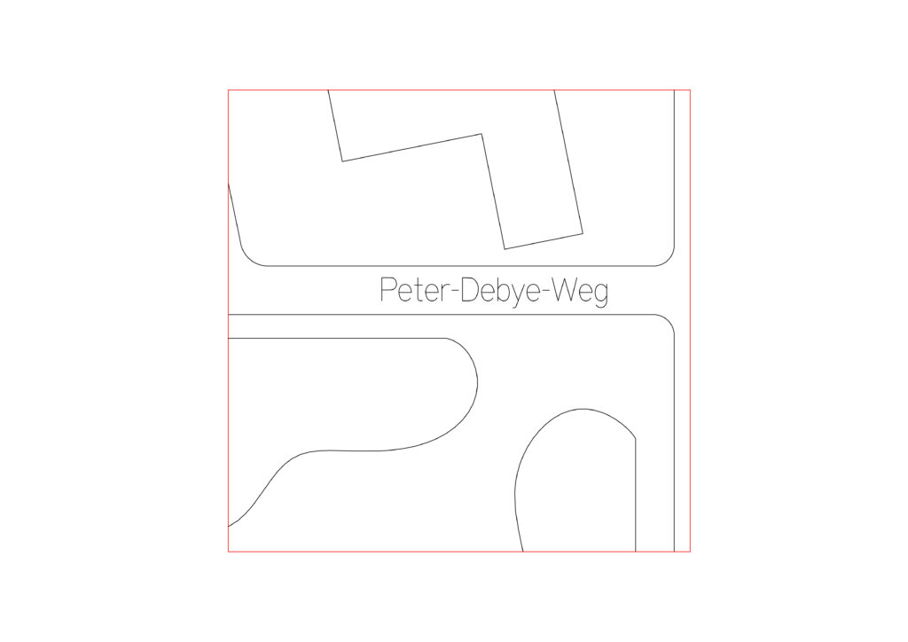
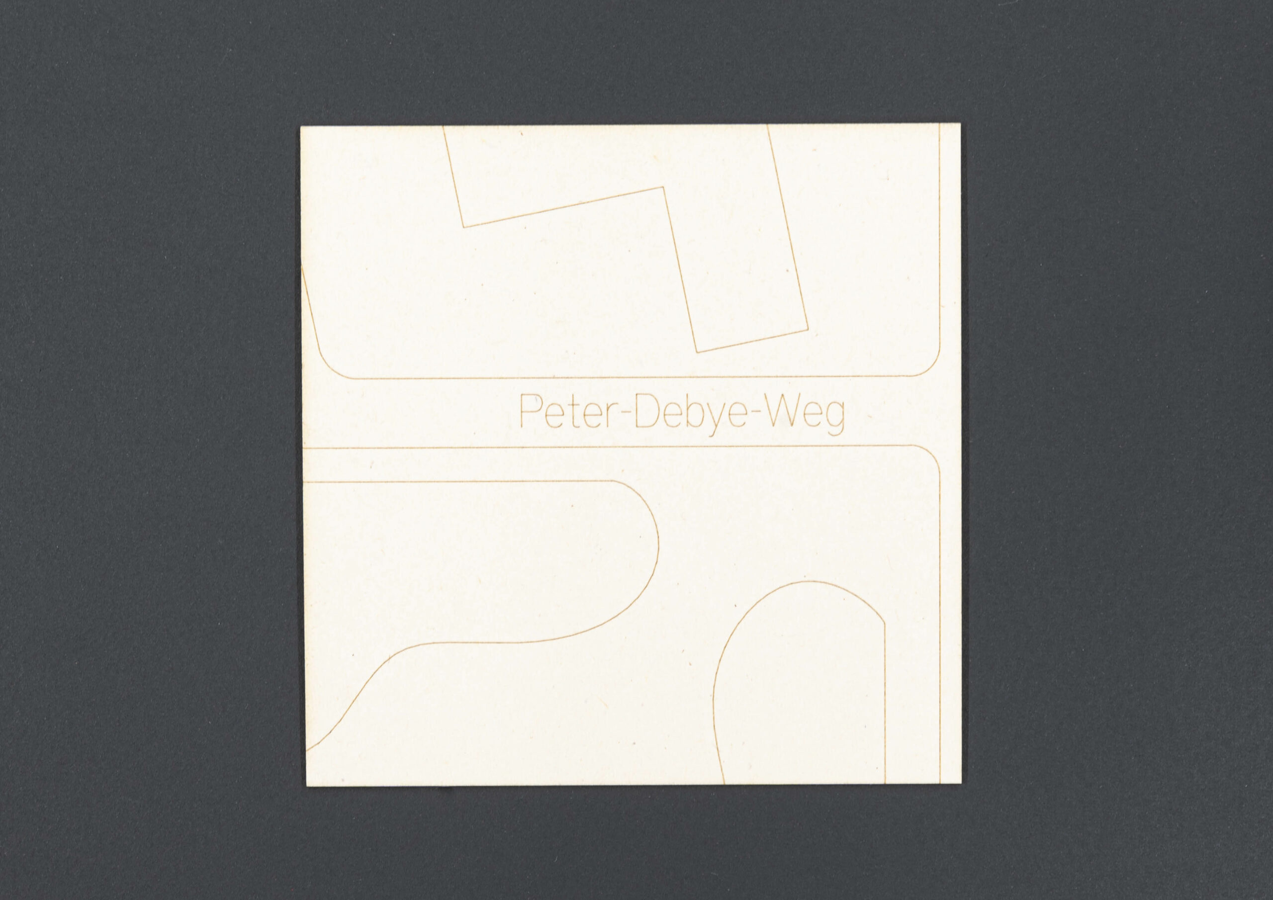
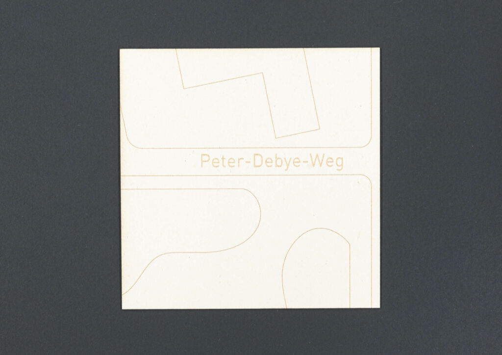
Vector Engrave
The laser follows the vector lines and draws them as a single line.
You can only use vector lines for the vector engrave setting.
The Line weight is ignored by the software.
Single line text (SLF-RHN Architect)
Text laser time 10s
Physical Example
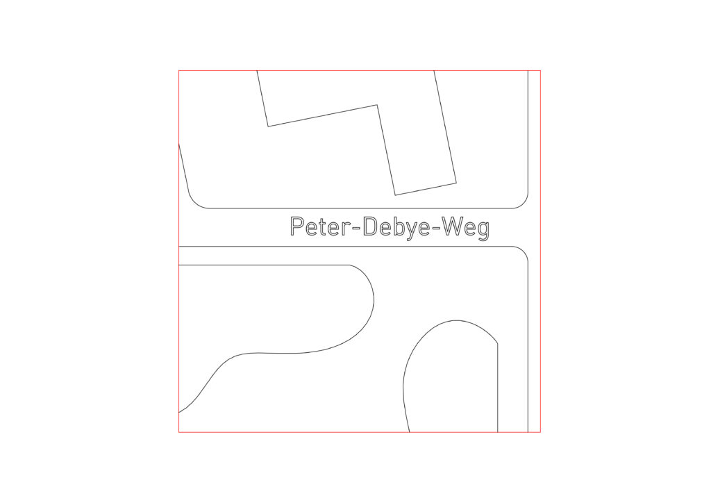
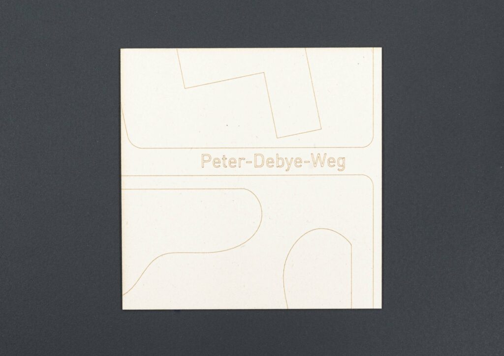
Outline text
Text laser time 19s
Physical Example
Raster Engrave
Raster engraving is created by the laser scanning the engraved areas very much as a printer does, filling the area to be engraved line by line.
Used when to engrave an area, for example a QR code, a surface, or an image.
The line weight of vector lines can be adjusted to engrave a thicker line.
Raster engrave is very time consuming and should be avoided during the end of the semester unless it helps to increase fabrication speed. In some instances, especially when there are many small individual lines that make up a texture or pattern it can be better to use the raster engrave.
Raster Text
Text laser time 14s
Physical Example
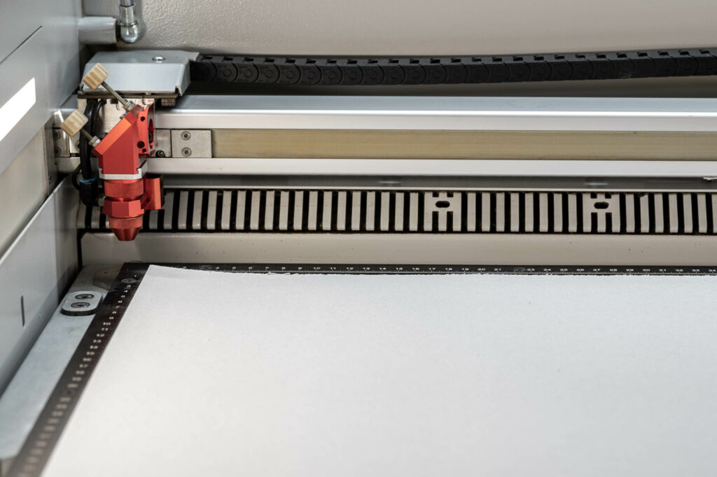
Keeping the material Flat
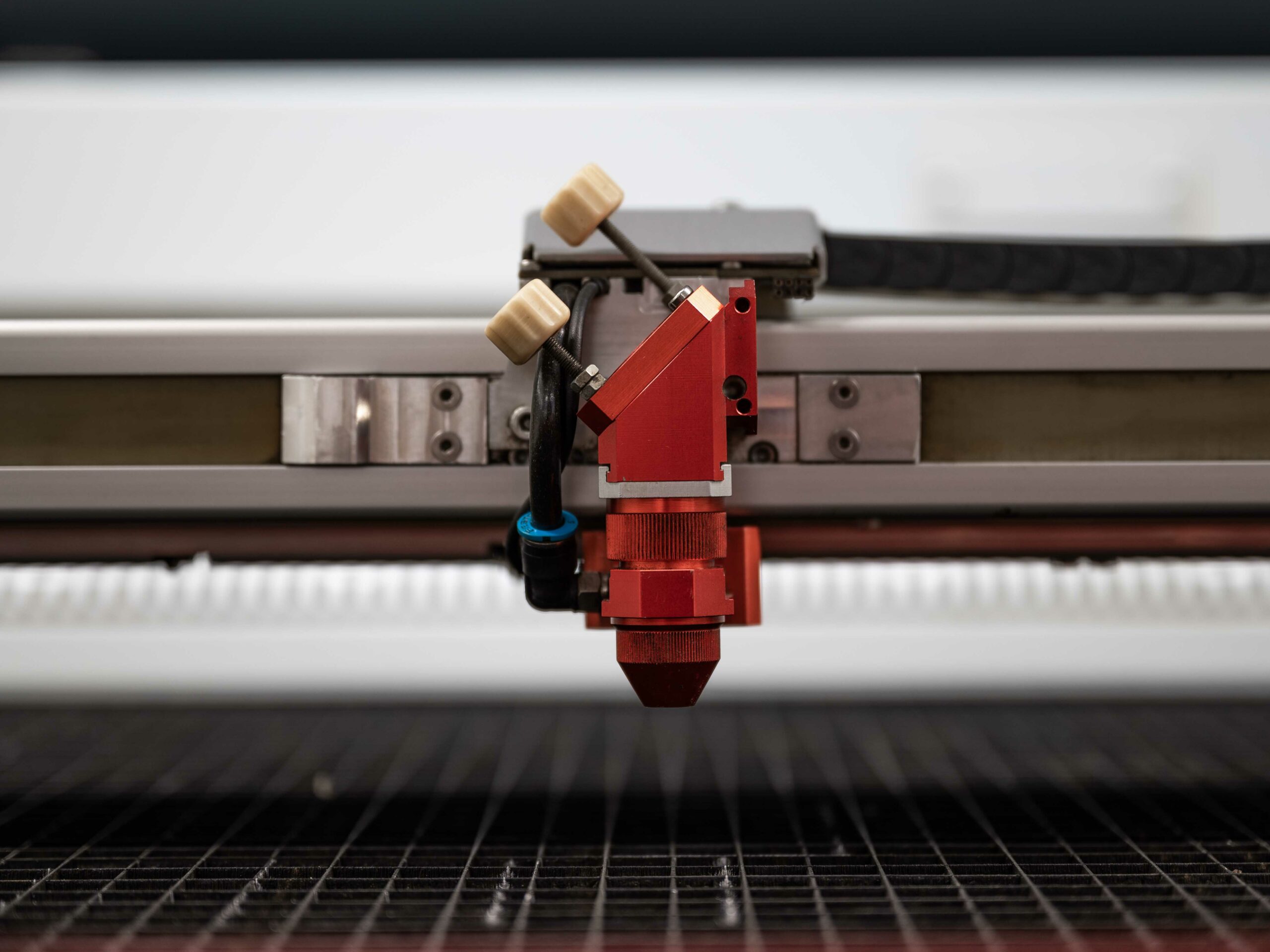
If the machine bed of the laser cutter is out of focus by 1mm it can affect the quality of the cut to the point where it is no longer cutting through the material.
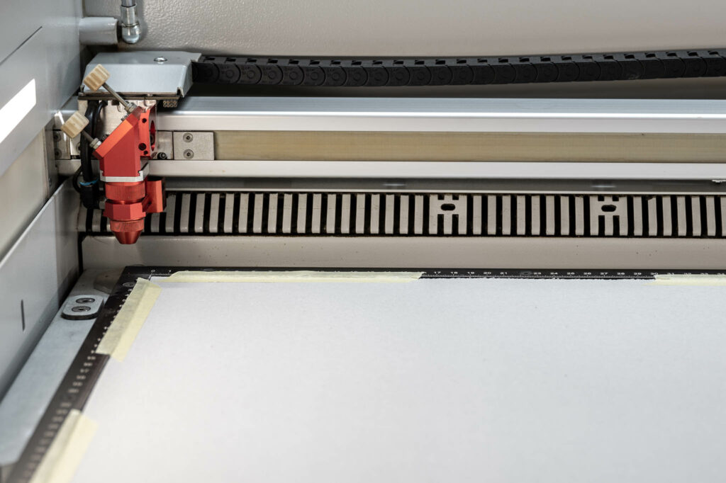
Therefore, it is important that the material we are using sits completely flat on the machine bed. When using cardboard, this can usually be solved by using strips of masking tape around the edges against the laser bed border. If, however, the card is thick or you’re using plywood, this solution may not work.
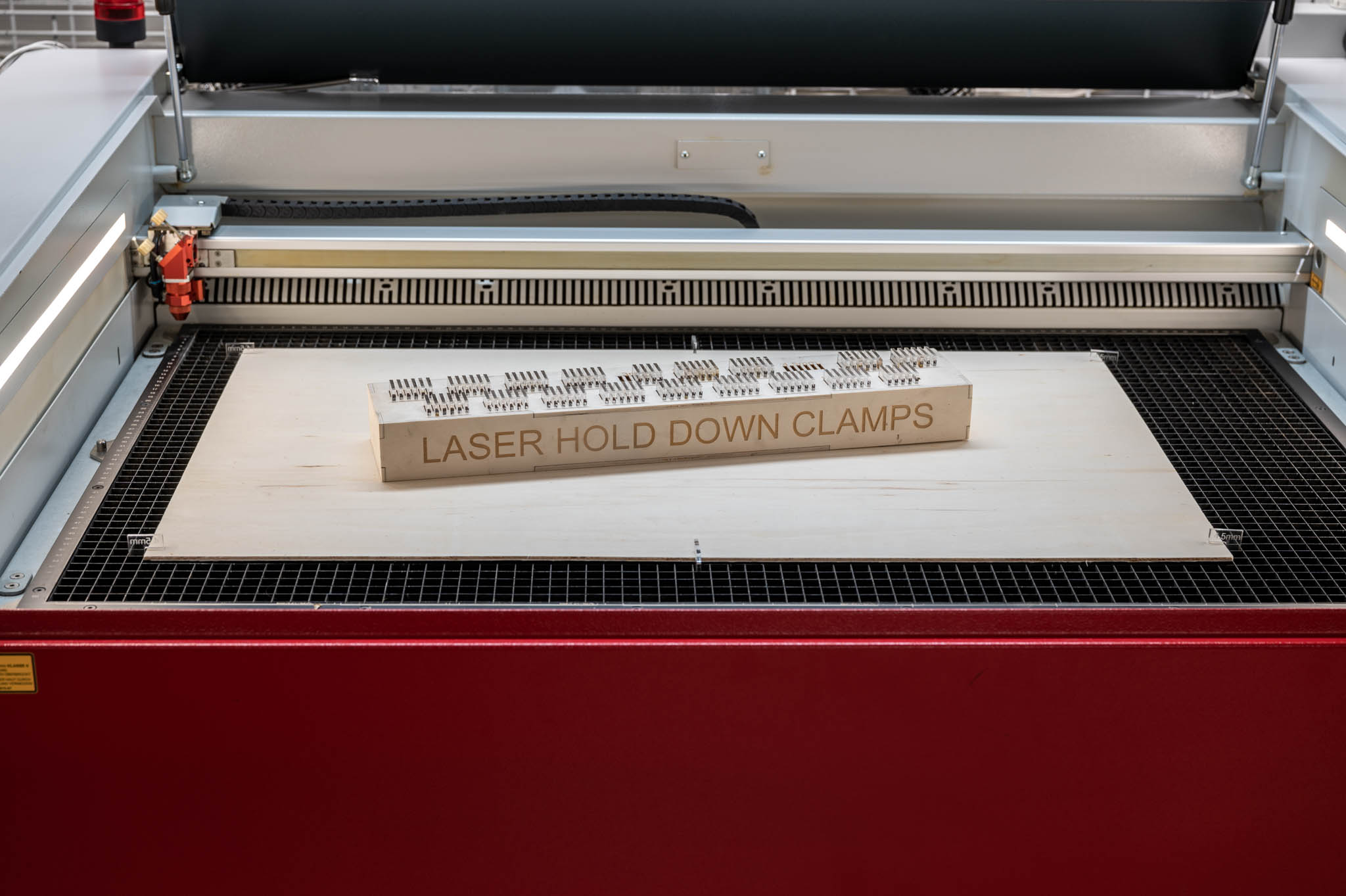
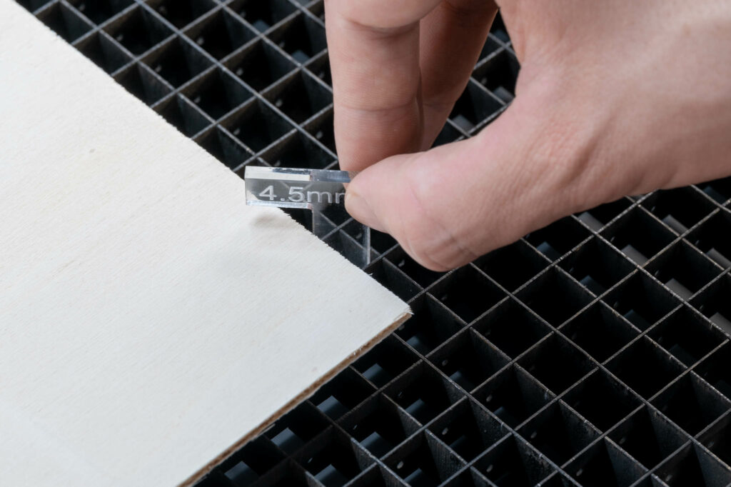
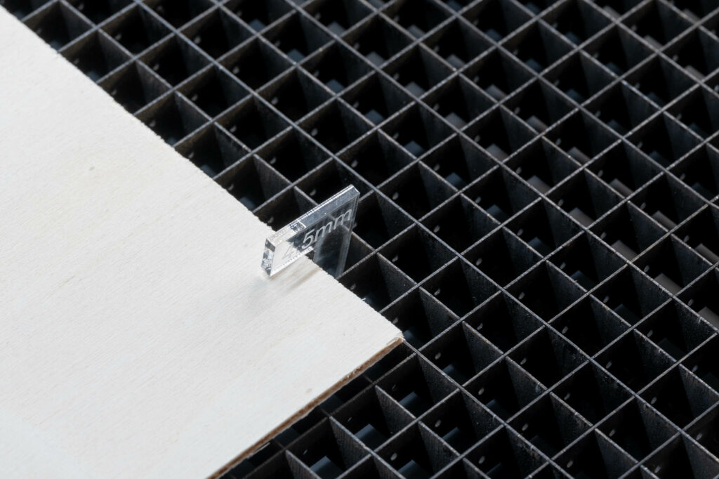
We use a set of laser hold down clamps that can be slotted into the laser grid to remedy this problem. Please be aware that that the material has to be 50mm smaller than the full bed in one direction to accommodate the clamps.
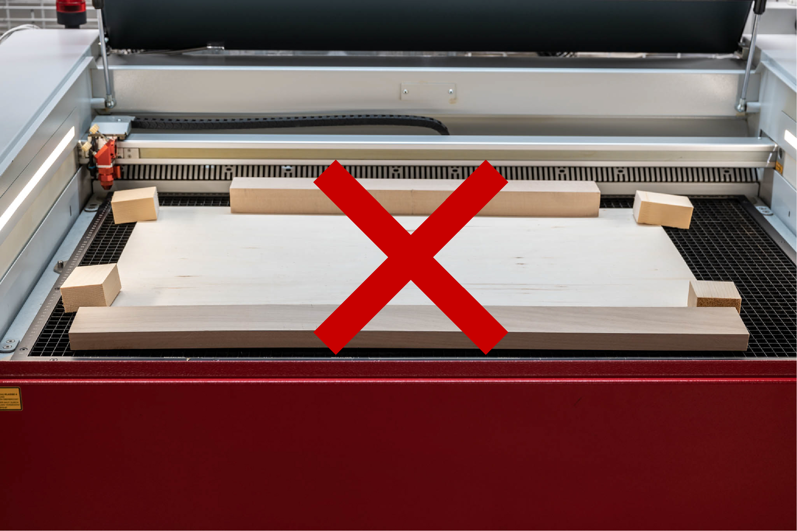
Never use blocks or other objects to weigh down the corners of your material. Starting the laser while something exceeds the nozzle height will result in the nozzle crashing into it and very likely cause damage to the machine!
The ability to simply send a 2d vector-based computer file to the machine and very quickly cut complex geometries from sheet material makes digital cutters the most popular tools in architectural modelmaking workshops. (Hard edge modeling)
Most architectural elements can often very easily be broken down into 2 dimensional profiles which can be cut from a variety of material thicknesses. With very little effort ideas can manifest in the real work which makes these tools such a valuable resource.
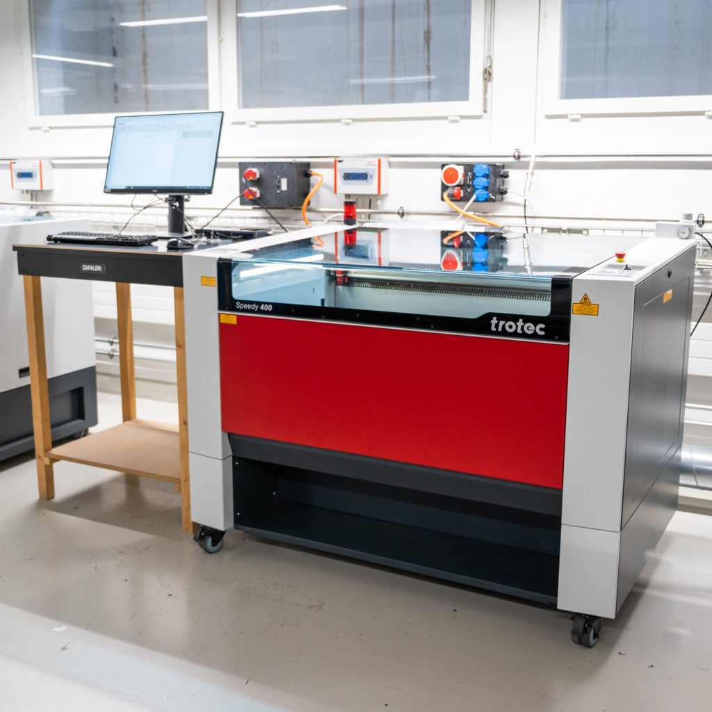
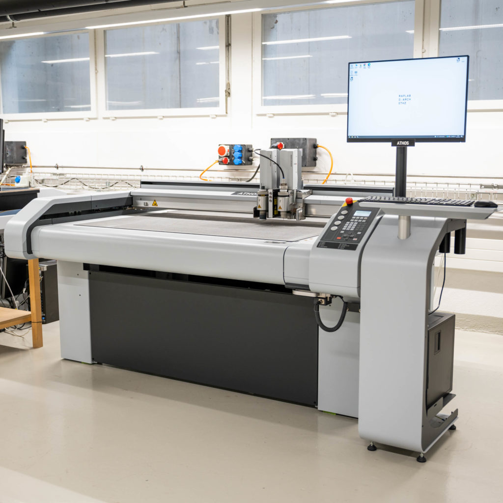
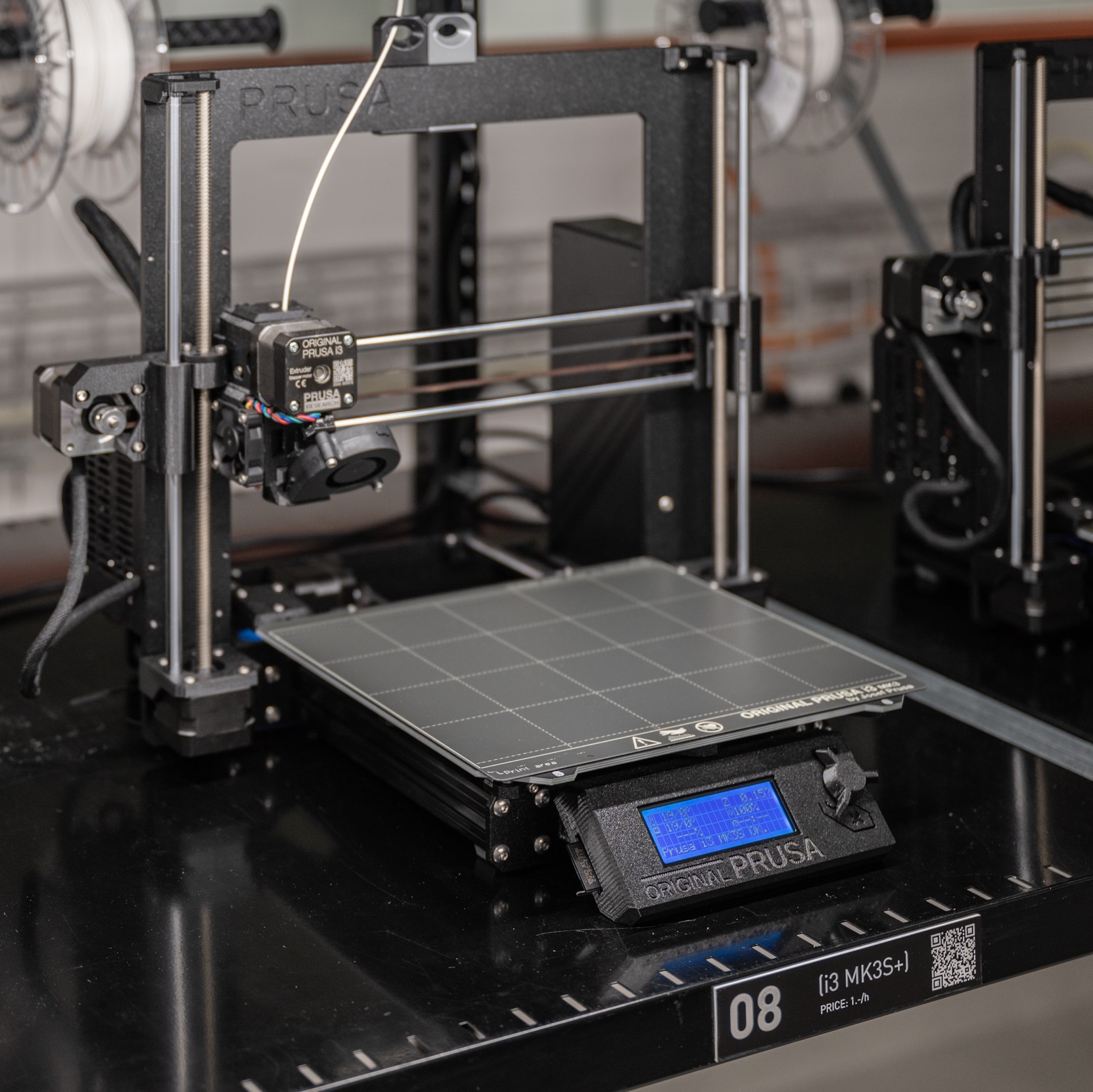
The 2 machines that will be available in the Raplab on completion of the moodle course are Zünd Cutters and Trotec Laser Cutters.
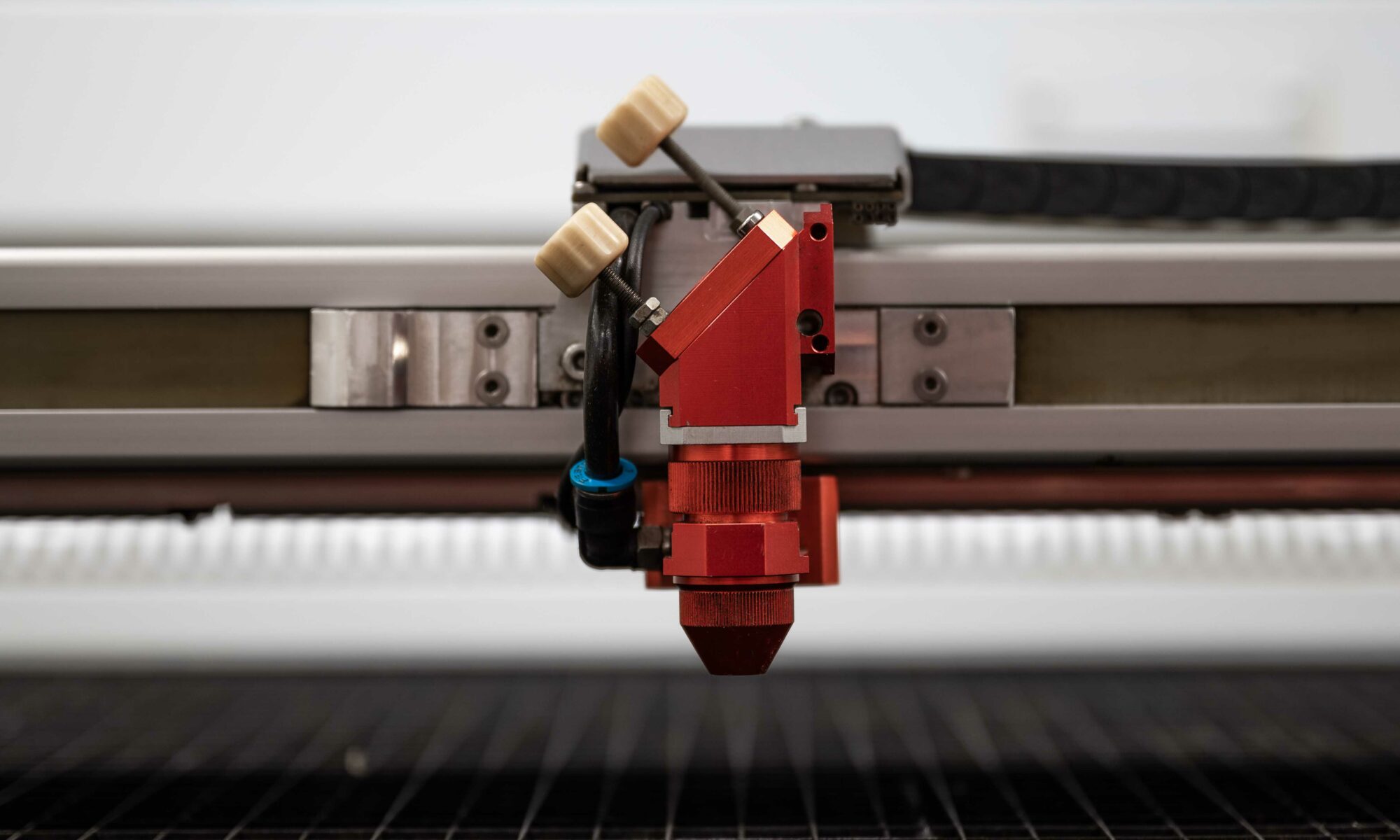
Trotec Laser Cutter
Zünd Cutter
File Preparation
The process of preparing a file for the laser cutter or the Zund plotter is the same until the point of where the parts are laid out.
For both cutters:
PDF and DXF Files are Acceptable. (2D Vector files)
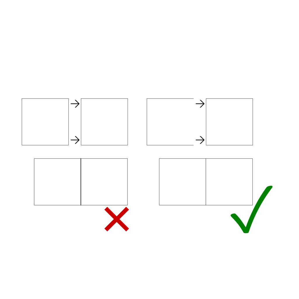
File should not contain any double lines. A double line is when there is more than one line in the same position.
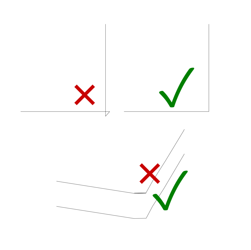
Shapes that should be cut out of the material should be drawn as a closed polyline or closed curve. This ensures that the endpoints meet and there is no unnecessary over cutting of the shape.
Polylines or curves should be going in one general direction. If we have a closed curve, it should go only clockwise or anticlockwise. Not both. The line should not go back on itself. This can cause machine errors.
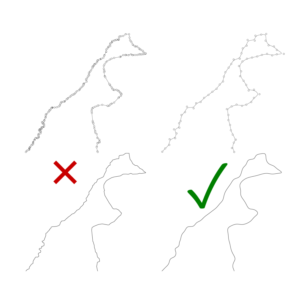
A curve or polyline should not be made up of any segments smaller than 0.2mm. This is too much information for the machine to process. This can also cause machine errors.
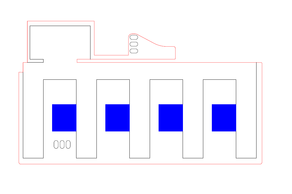
Parts to be cut should be red – 255, 0, 0
Engraved elements should be black – 0, 0, 0
To use the cutters special feature use blue 0, 0, 255. (Zund – Pen – works with vector lines only) (Laser – Raster Engrave – Works with vector lines, filled areas, hatches and even images)
Only Export the information that is to be cut or engraved. No hidden information such as empty text boxes or watermarks. These can cause errors.
Rhino tip – Use command “SelDup” to reveal the double lines
3D geometry such as surfaces or meshes need to be converted into lines, arcs, and curves as this is the only format that can be read by the machine when cutting.
Rhino tip – Curveboolean is a powerful tool to extract closed polylines and curves from an existing 2D plan.
Things to look out for when preparing files for digital cutters:
No double lines (duplicates)
Double lines are the result of 2 or more lines that are on top of one another.
Avoid curves that intersect with themselves and curves that go back and forth on the same path.
This can cause machine errors due to the quick change in direction
Try to keep the complexity of curves and polylines down. This can be done using the curve rebuild tool in rhino
Avoid curves that have extreme short segments (<.2mm).
You can make a check in rhino using the selshort command and then fix the issue using the curve rebuild tool.
Check out our grasshopper patch that will allow you to rebuild many lines in one go. You can download it here
Acceptable Materials
The following materials are acceptable materials to be cut in the digital workshop:
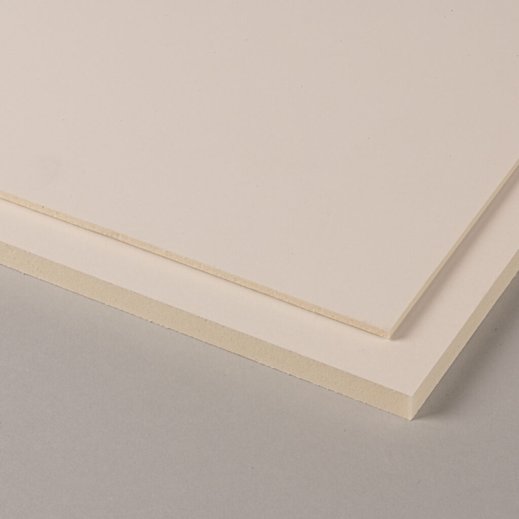
Foam board
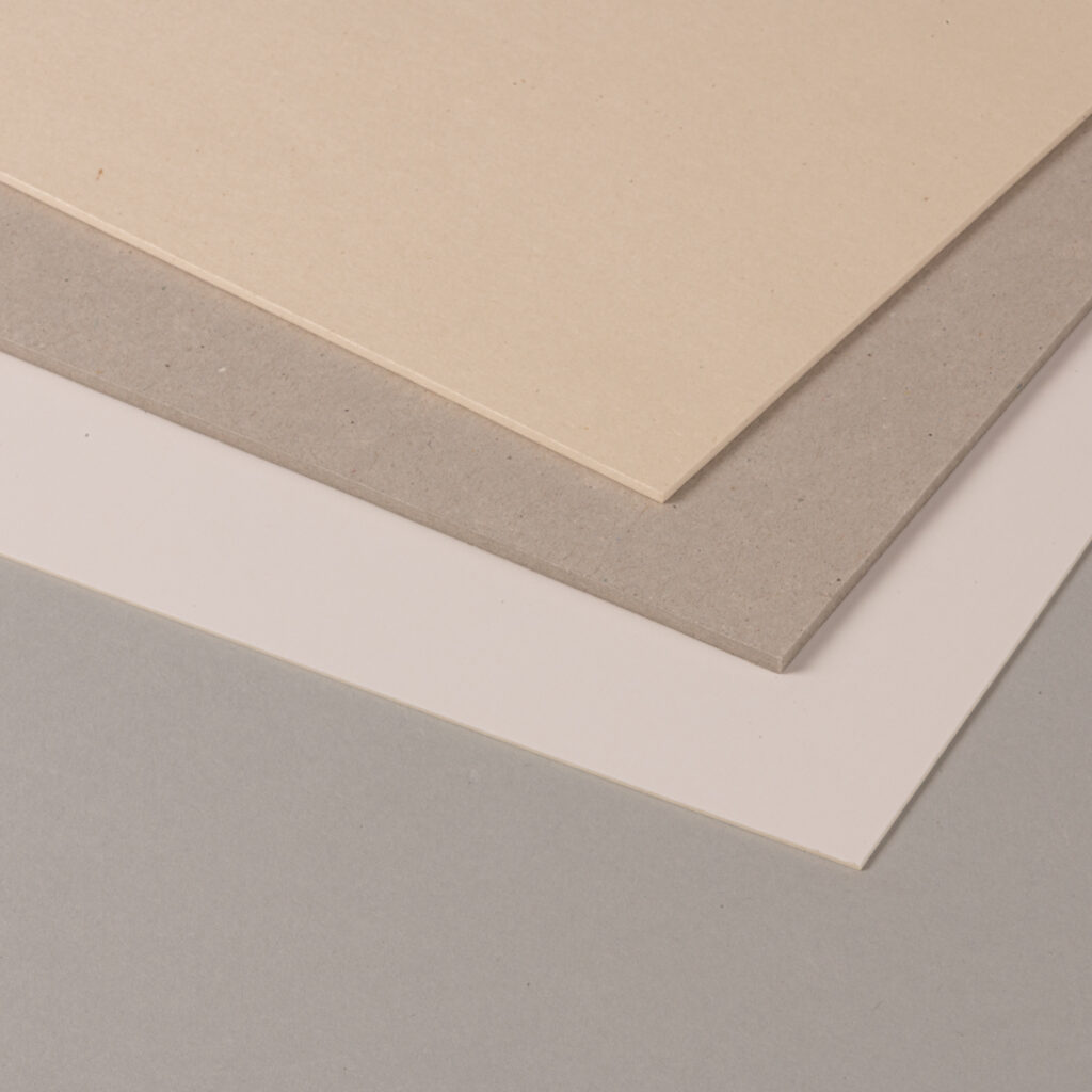
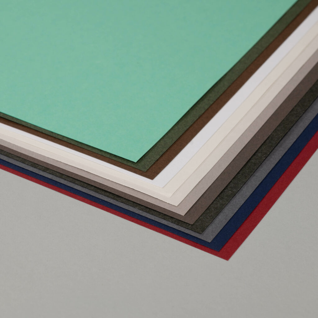
Cardboard
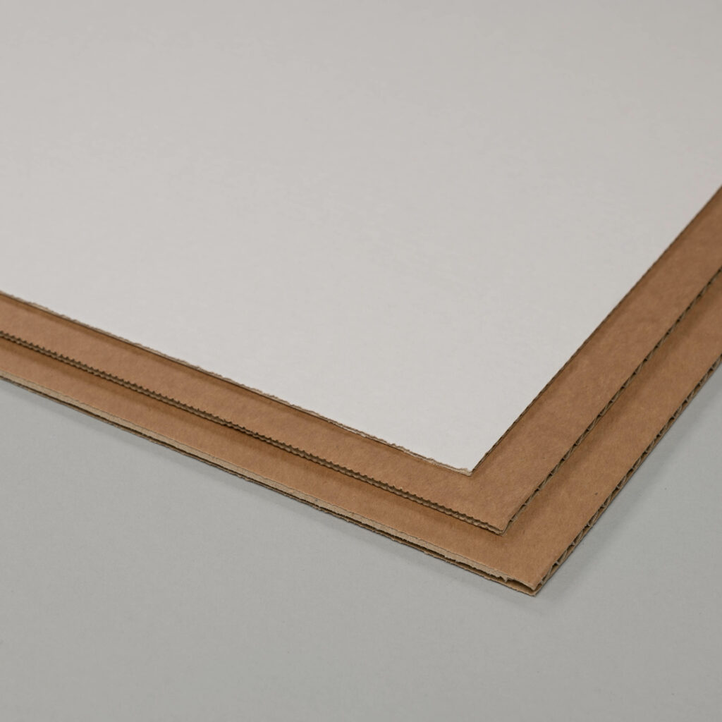
Corrugated Cardboard
Paper
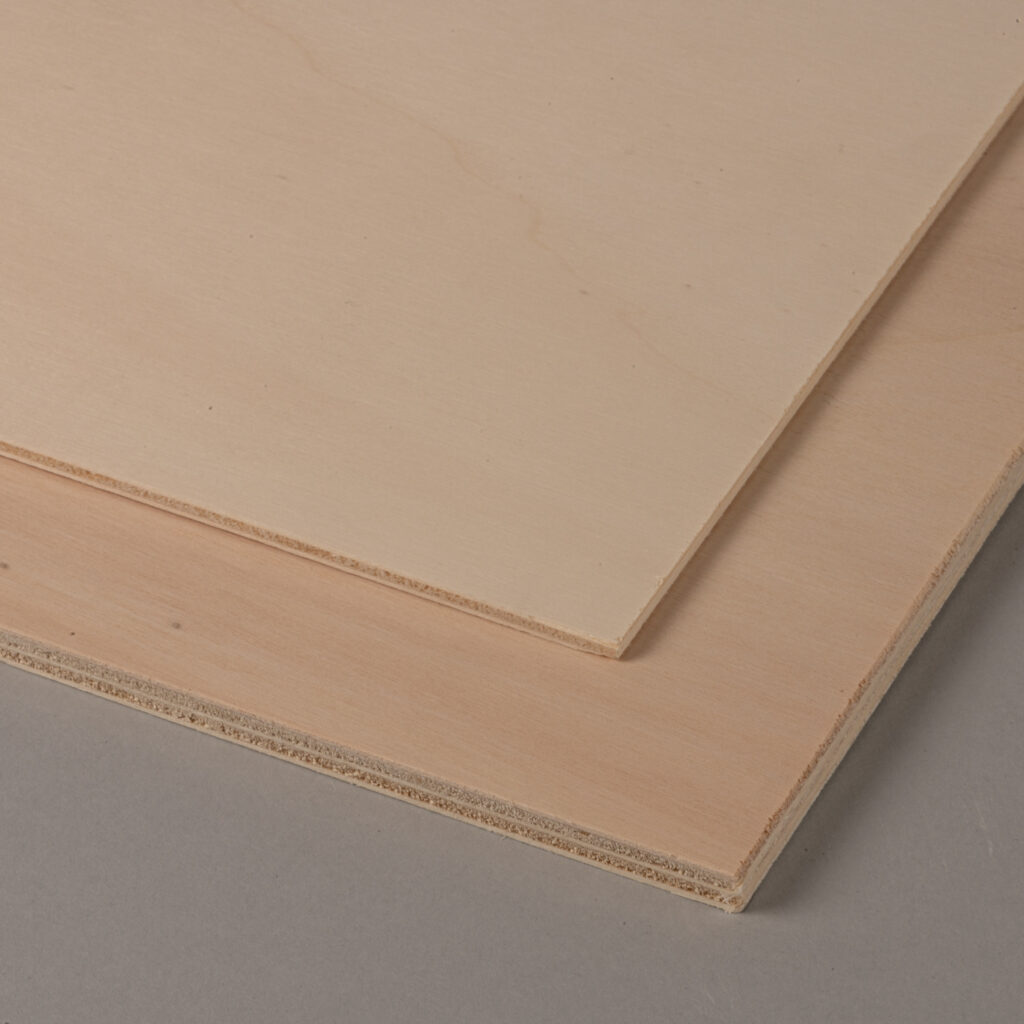
Plywood
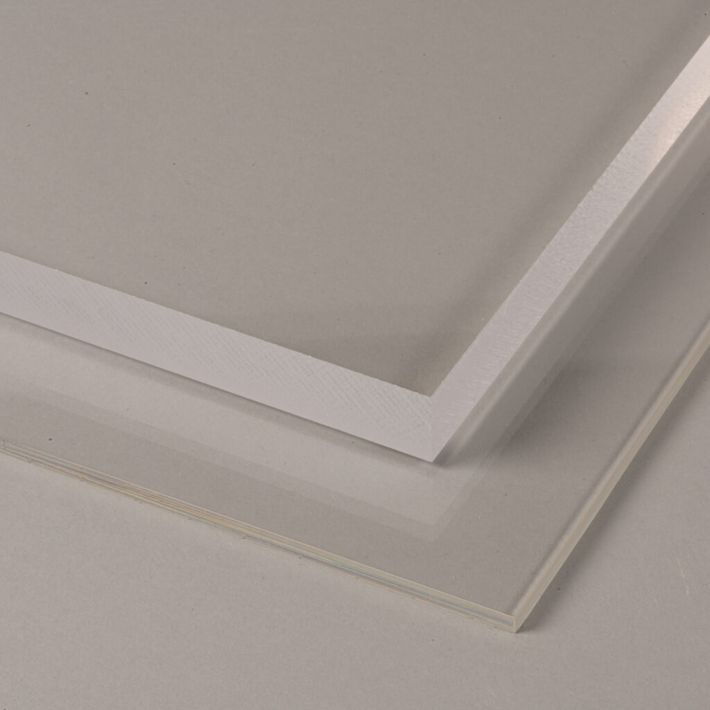
Acrylic
Materials not listed are not permitted as they can cause toxic fumes and cause damage to the machine.
Always double check that the material is compatible with our machines before purchasing.
Foamboard - Zünd
For the Zünd only. Comes in black and white. Cuts very cleanly. A good option for thick elements that must be accurate.
Cardboard - Zünd and Laser Cutter
Can be cut on both the laser and the Zünd machine. The laser will leave a burnt edge whereas the Zünd will not.
Corrugated Cardboard - Zünd and Laser Cutter
Can be cut on both the laser and the Zünd machine. The laser will leave a burnt edge whereas the Zünd will not. However the burning with the laser is less evident than with normal cardboard.
Paper - Laser Cutter
Paper cuts rather well on the laser cutter with minimal burning. The burn is almost invisible on darker coloured paper.
Plywood - Laser Cutter
There are two types of plywood allowed to be cut in the digital workshop. Poplar plywood and Airplane Plywood (thin birch plywood). Please make sure you are using these types in the laser and not any other variants.
Acrylic - Laser Cutter
The only plastic that we allow is Acrylic. Double check the label before purchasing. The purchase of the wrong material is a very common mistake. There are many different types of plastic that exist that look very similar and are not machine compatible.
Hobby Glas > Polystyrene
Makrolon > Polycarbonate
Vivak > Polyethylne
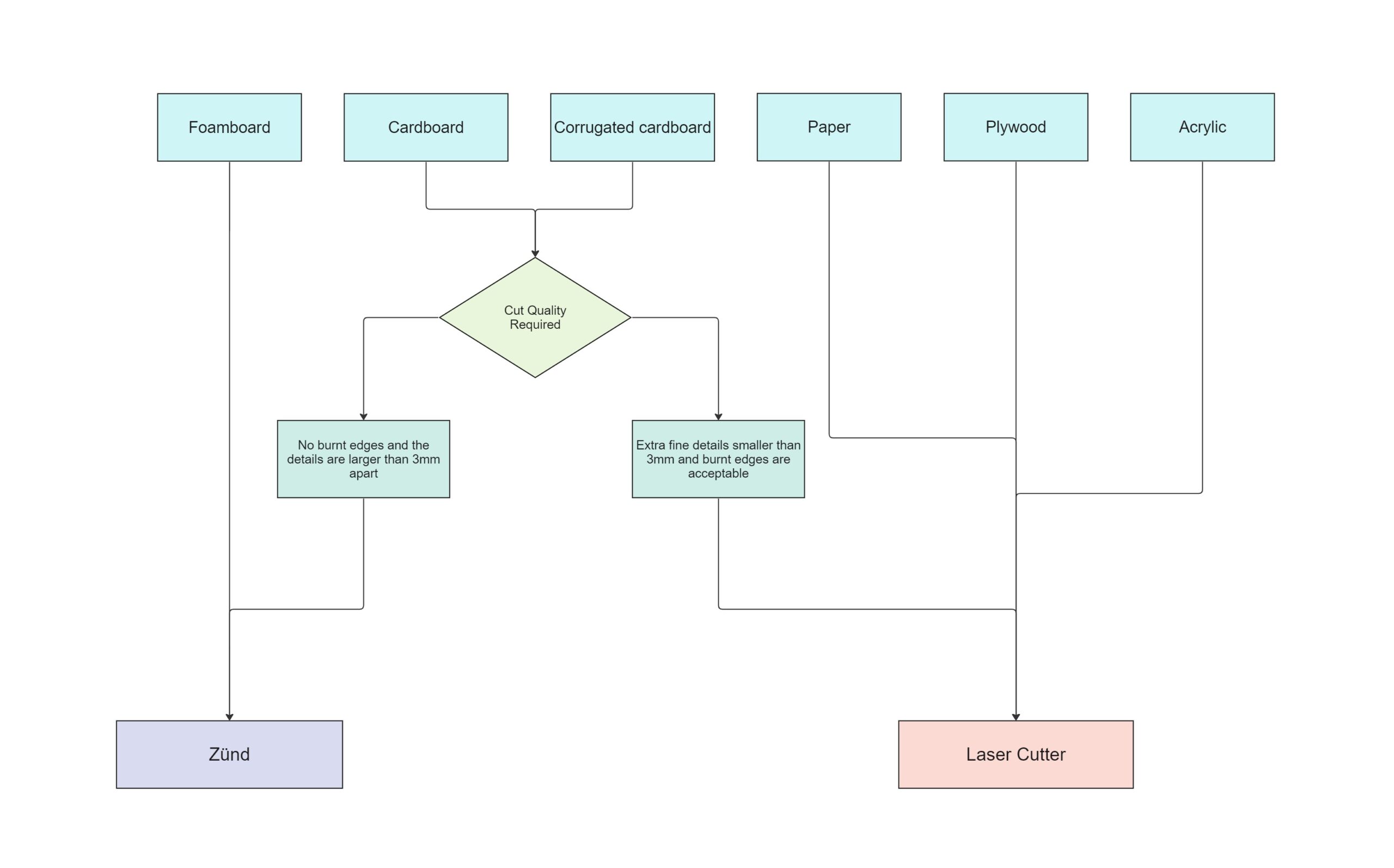
Laser Vs Zünd - Considerations
The material choice will usually dictate which machine you that you must use. However, if you are using cardboard or corrugated cardboard, then both machines are acceptable. They will give a similar outcome to one another, but there are some differences that you should take into account before choosing between the Laser and the Zünd.
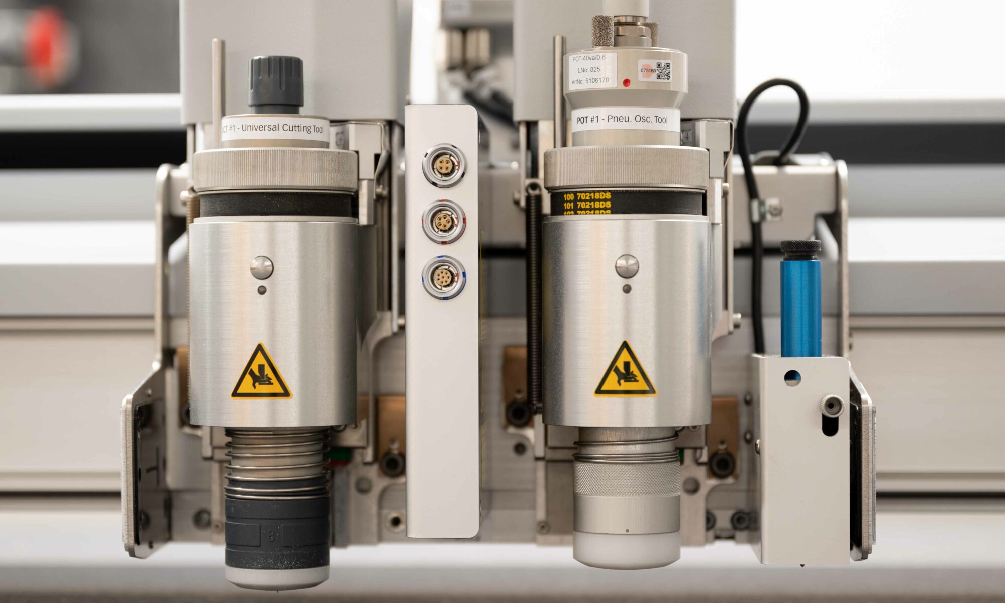
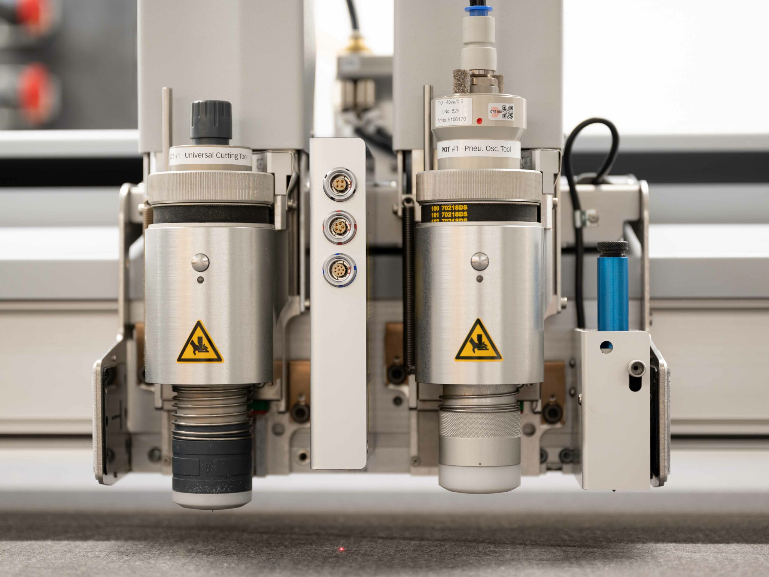
Zund Cutter
The Zund is a modular cutting system which can be adapted to use many cutting or mark making tools. In the digital workshop we have both of them set up with a pen and 2 types of knifes. One drag knife for cutting through cardboard and an oscillating knife for cutting though corrugated cardboard and foamboard. (the correct knife will be utilized when the material is selected in the rhino software)
Does not leave a burnt edge
Can not cut details smaller that 3mm
Can cut cardboard, corrugated cardboard and foam board
Can not cut radii smaller than 4mm
Has the option of using a pen
The inside corners are slightly overcut
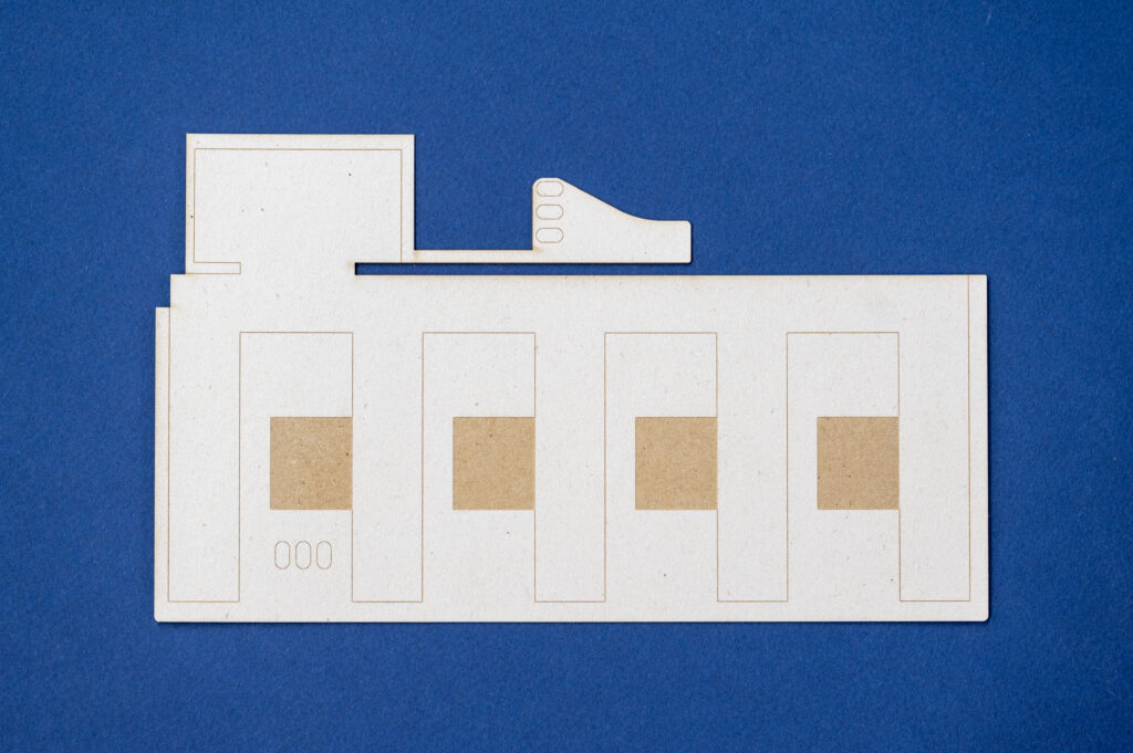
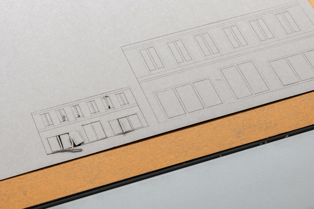
If cut or engrave lines are too close to one another, the top layer of the card can become delaminated or result in the parts being lifted off the machine table by the cutter. Notice the façade detail at half the scale has failed as the details are smaller than 3mm apart. This also needs to be taken into account when laying out small parts. They need to have at least a 3mm space in between them.
Due the the geometry of the knife it slightly overcuts the inside corners. This is more prominent on thick material. It can sometimes be a good idea to mirror your parts and flip them afterwards if there is no engraving required.
Another consideration is the engrave quality. (from left to right)
Zund pen
Laser Engrave
Zund Engrave
Laser Cutter
Laser cutting is a type of thermal separation process. The laser beam hits the surface of the material and heats it so strongly that it melts or completely vaporizes. Once the laser beam has completely penetrated the material at one point, the actual cutting process begins.
Leaves a burnt edge on all material except Acrylic
Can cut details smaller than 3mm
Can cut paper, cardboard, corrugated cardboard, Plywood and Acrylic
Has raster engraving as an option.
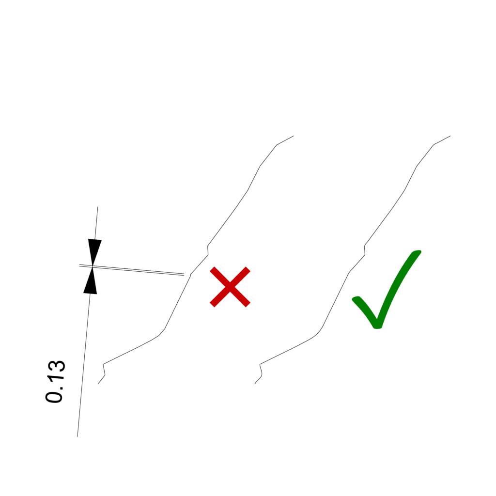
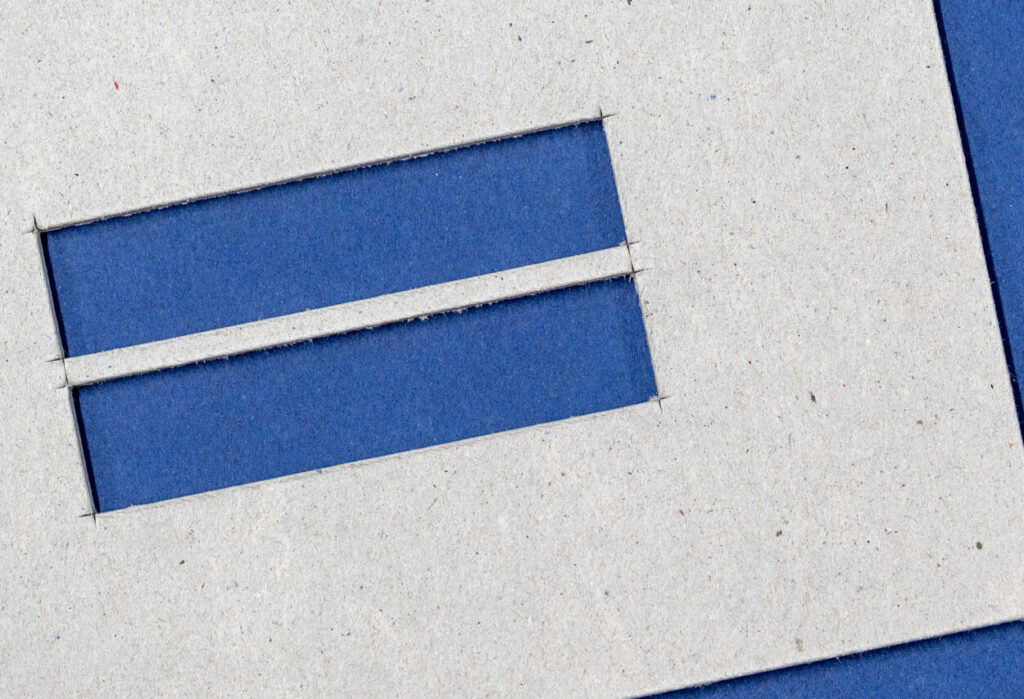
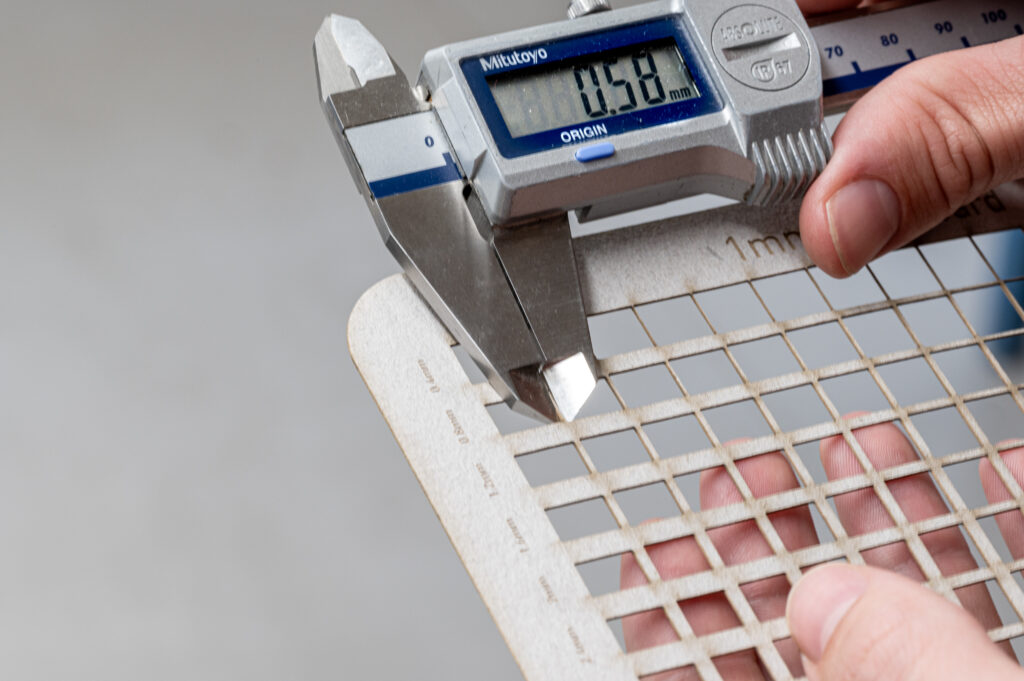
The laser removes between 0.1mm to 0.3mm from either side of the cut line. This is known as the laser kerf. In the above image we are checking the measurement of a sample which measured 0.8mm in the drawing and 0.58mm in reality.
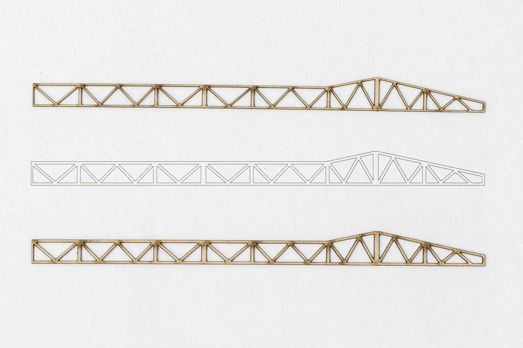
When cutting very fine details (less than 1mm wide) it’s a good idea to offset the lines outwards to beef up the parts slightly.
The cut part without any offset
A printout of the original file
The part cut again with a 0.1mm offset in the drawing
Notice how the part with an offset looks closer to the original file.
FDM 3D printing offers currently the best value in model and prototype making due to its relative ease of use, speed, print quality, and price. Depending on the application it can either be seen as a technique for drafting or for making functional parts, giving the user a wide range of possibilities. FDM is a process whereby a heated extruder deposits the first layer plastic onto a build plate and the successive layers onto the one previous. At the Raplab we have our printers set up with white PLA only.
Pros
A very inexpensive process
Machines are very affordable and therefore easily accessible
Print time can be rather quick if done in a considered way
The print material, PLA, is recyclable
Cons
Requires support material on overhanging parts
Layer height is usually larger than other print methods giving visible lines on the print surface.
Unable to achieve a super high level of detail
May not produce extremely complex structures due to the amount of support material required.
File Preparation
The File format most commonly used in 3d printing slicer software is an STL mesh, which is a representation of a 3-dimensional surface in triangular facets. This file format contains information about the inside and outside of the 3d model. Therefore, it is important when exporting a 3d model to STL, that the model is completely closed, solid or “watertight”. Otherwise, the software won’t be able to distinguish which part of the model is inside or outside during the export. Thus, unable to know where to place the infill.
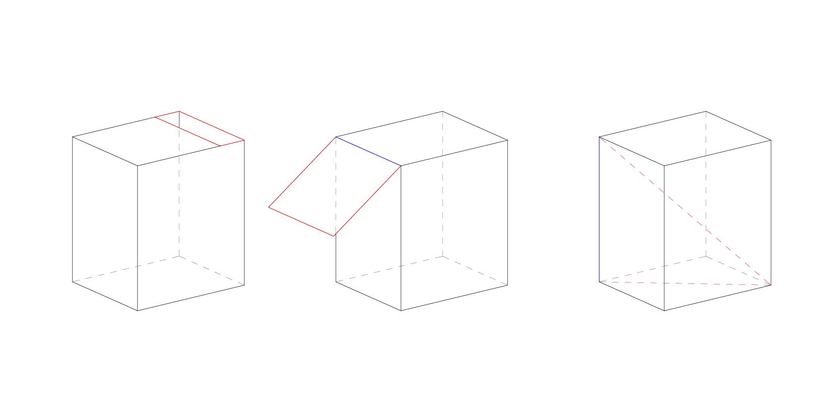
Below, naked edge and non manifold edge.
The model should have no manifold edges (blue). This is an edge should not be made up of more than 2 faces.
It also shouldn’t have any naked edges (red). A naked edge is made up of only one surface. If the model has a naked edge then it is by definition not solid or watertight.
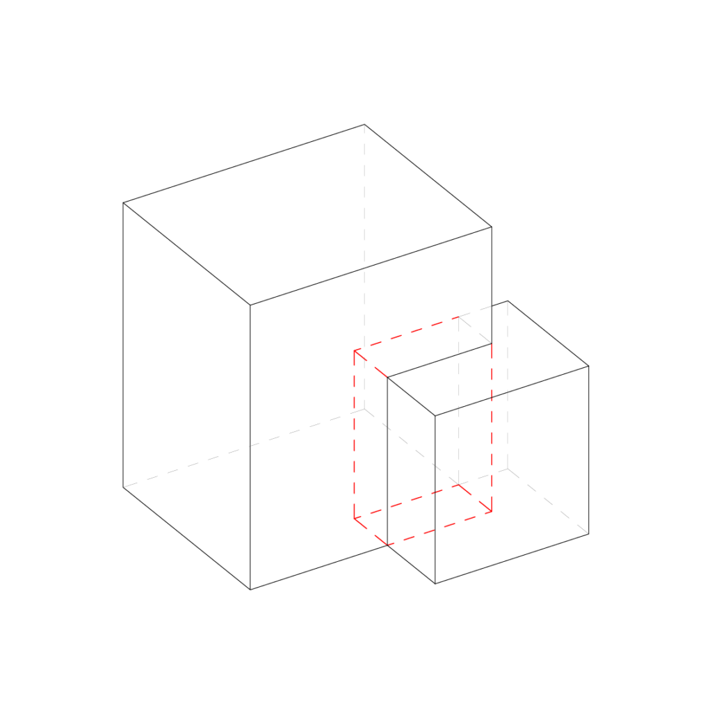
It is also very important that the 3d model doesn’t have any intersecting parts.
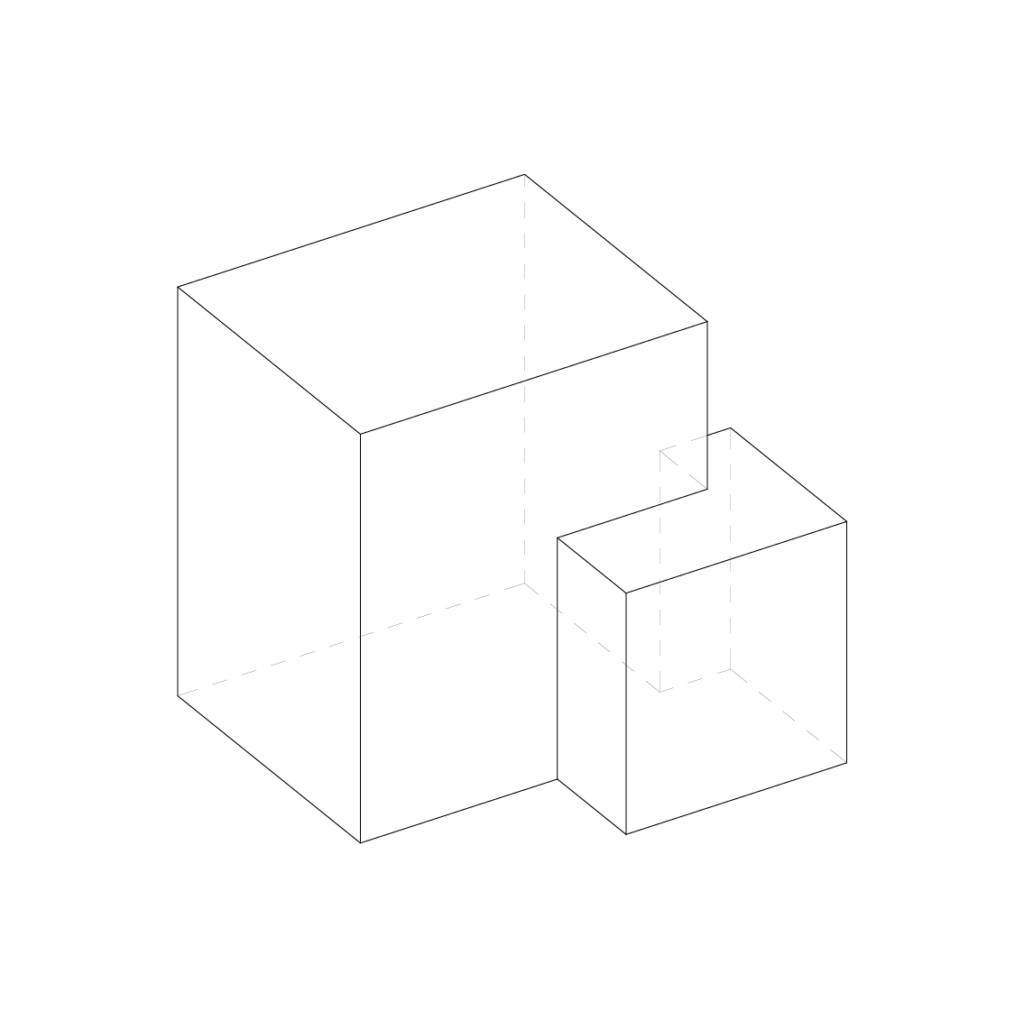
If you have more than one part, it is best practice to export them as individual STL files. This gives more flexibility when preparing the print in the slicer software. Multiple parts can then be arranged on the build-plate. The slicer will also automatically make all the bottom surfaces that are meant to be attached to the build plate co planar. So we don’t have to worry about where models are in the world coordinates
Export Checklist
The object must be a closed poly-surface or mesh
No non manifold edges or naked edges
No intersecting surfaces
Individual parts should be exported separately
The model must be smaller than the printers build area – It can be split if necessary
Rhino tip – Check edges by using the command “show edges”. Then the box’s naked edges.
Slicer Software Guide
Understanding the limitations of the machine and how to get the most out of it will allow for some very effective results. Here we will outline some 3D printing terminology as well as giving tips and tricks to help reduce time and increase print quality.
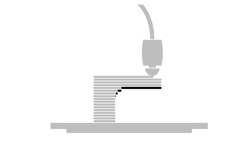
Overhang
FDM 3d printing is a process in which a layer of extruded plastic is placed on top of the previous one. Each new layer must be supported by the one beneath it. If the next layer extends outside the boundary of the previous one, this is known as an overhang.
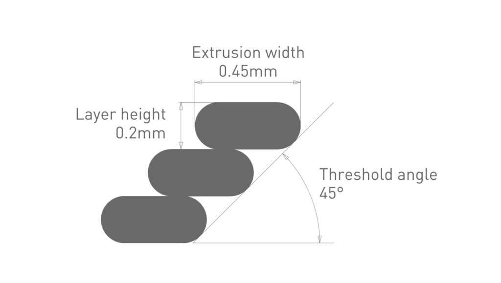
Threshold angle
Threshold angle is a term to describe the amount of overhang. The smaller the angle, the larger the overhang.
With the default settings of 0.2mm layer height with the 0.4mm nozzle, the extrusion width is 0.45mm. With these settings the printer is able to achieve an overhang of 45 degrees without the need for support material. This is because there is still just enough contact with the previous layer. If the angle decreases the print is likely to fail as there is not enough underneath to support it.
Support material
Support material is a printed structure, usually in a lower density than the supported object, so it can easily be broken off. There is also a slight offset from the object, so it doesn’t adhere too strongly. Support material is not waste and can be recycled.
However due to the nature of the process the surface quality of the part touching the support is compromised. Utilising support material also massively increases the print time and material used. Therefore, it should be avoided if possible.
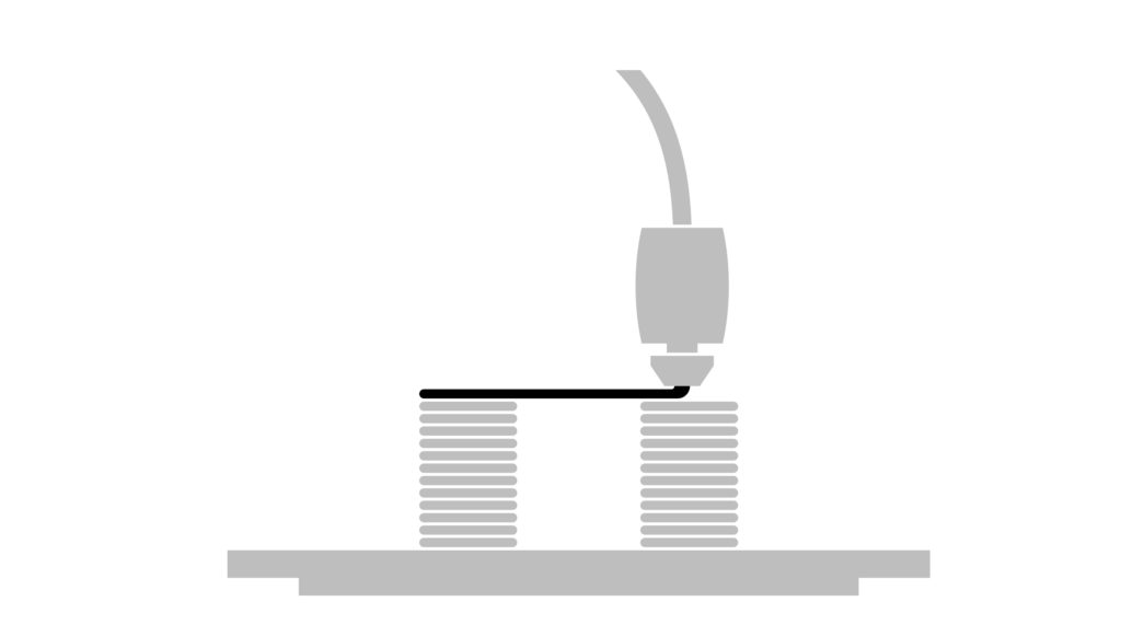
Bridging
Usually, it isn’t possible to print an unsupported layer without anything underneath to support it. Whether that be support material or the previous layer. If the toolpath of the unsupported part is going in one direction and is supported at either end, the printer can print in mid-air over short distances. This is known as bridging. The 3Dprinting slicer will automatically optimize the toolpaths to make this happen.
Avoiding support material
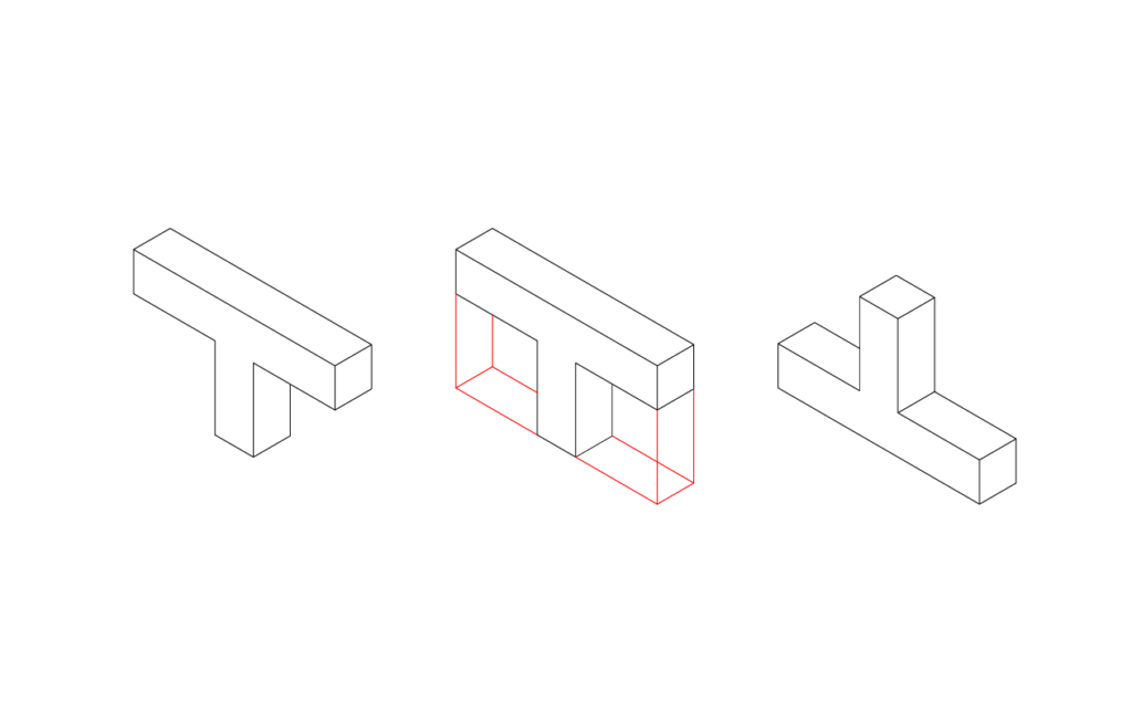
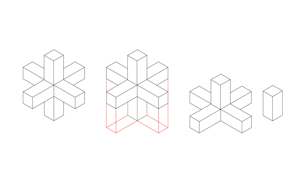
Flipping or splitting your part can remove the need for any support material. It may seem counterproductive splitting a model as it would then have to be glued together which means there is an extra step in the physical build. However in more cases than not, this approach makes a lot more sense in terms of reducing print time and improving print quality.
In the case of 3d printing we also want to have a large enough surface area attached to the build plate and splitting the model can often give us a larger surface area.
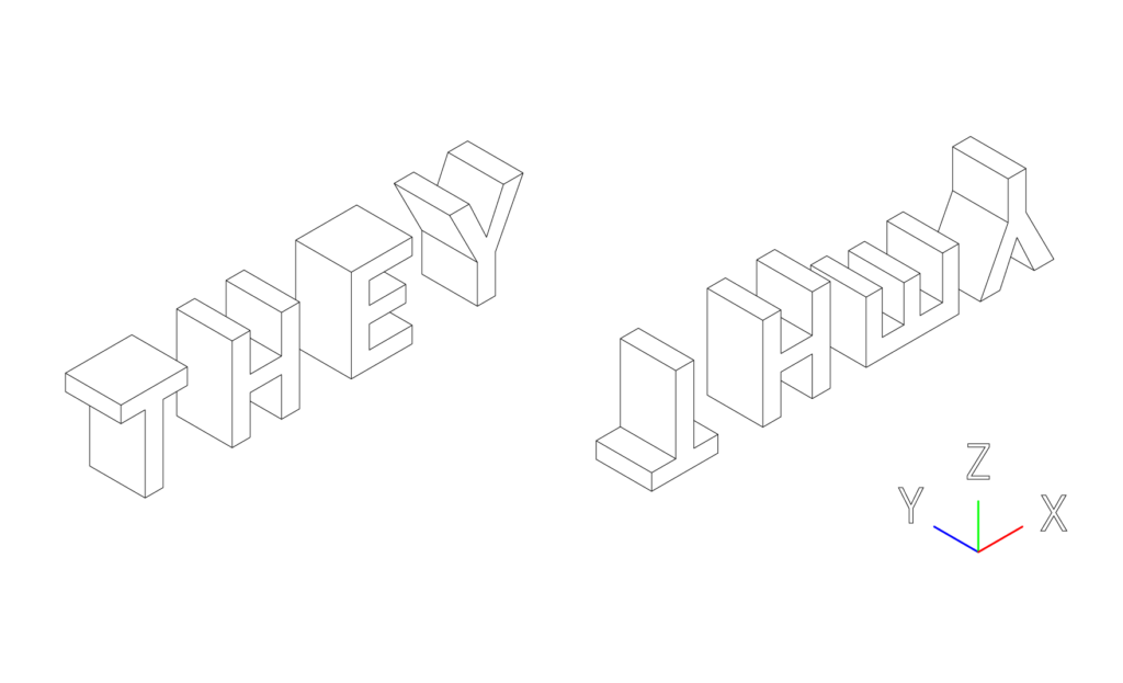
The “they” rule
Let’s imagine we want to print out the letters of the words THEY without support material 50mm high but we can only rotate them in the XZ orientation. For the purpose of the exercise, rotating in the YZ is impossible.
The letter T can be rotated 180 degrees so it is printed upside down.
The letter H does have an overhang. However this can be printed without support with bridging.
The E can be rotated 90 degrees.
And the Y would work fine as the threshold angle is greater than 45 degrees. However, it would be best to rotate 180 degrees to increase the amount of surface area attached to the build plate.
(Image of the normal orientation and the optimized orientation)
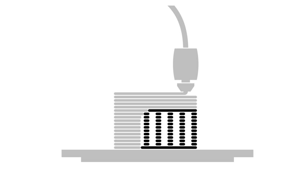
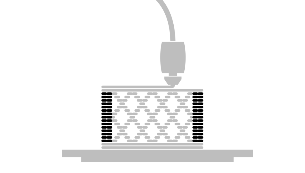
Vertical Shells
The vertical shells or sometimes named perimeters make up the vertical shells of your print. By default the slicer selects 2 layers.
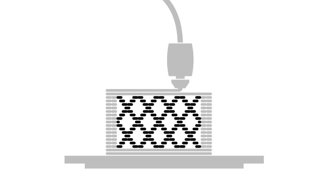
Infill
The part within the walls is called the infill. The purpose of the infill is to give the model some more strength but more importantly it’s there to support the top horizontal shells. Reducing the amount of infill can reduce the print time.
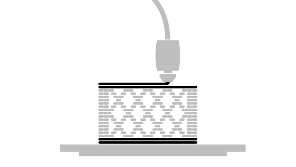
Horizontal Shells
The horizontal shells are the top and bottom layers of the print.
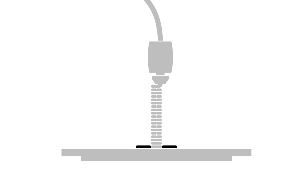
Brim
Sometimes the only option for printing an object will only allow for a small amount of contact to the print bed. In this instance it is best to use a brim to increase the contact area. This can be pealed off the model once printed.
Reducing Print time
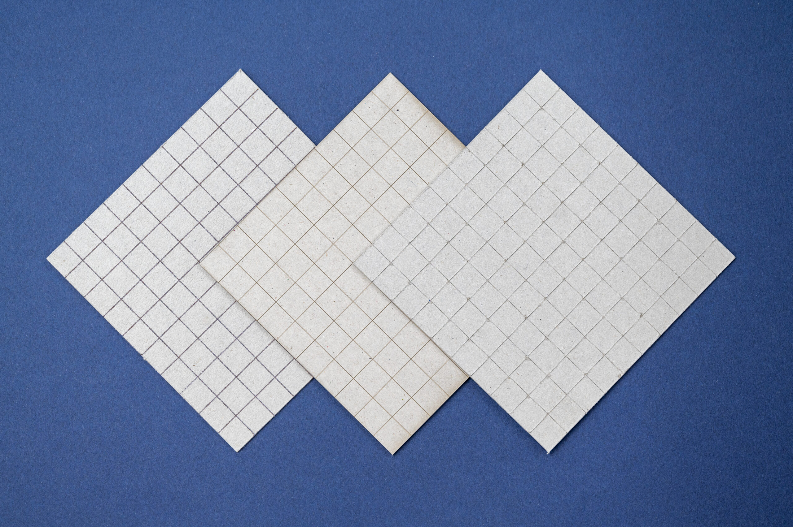
Increase Layer height
The most obvious way to reduce the print time is to increase the layer height. This will however give more prominent layer lines.
0.15mm – Layer Height – 52m
0.3mm – Layer Height – 28m
0.4mm – Layer Height – 22m
Spiral Vase
This removes one of the top horizontal shells and the infill from the model. It also prints a single perimeter in a spiral. It’s a good idea to use a slightly larger nozzle for this or adjust the print width in the advanced settings to 1mm.
Normal print – Printed same orentation as the photo.
0.4mm Nozzle, 0.3mm Layer height and infill 5%
9h53m
Spiral Vase print – Printed at 90 degrees to the orientation of the photo.
0.4mm Nozzle, 0.3mm Layer height
2h26m
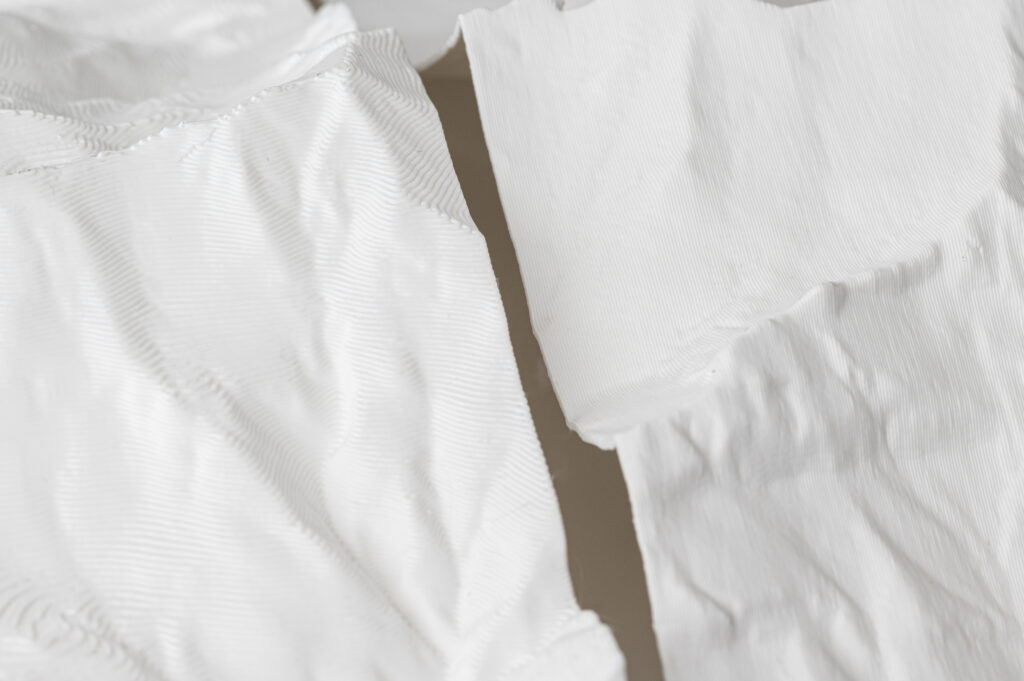
Tip – As the spiral vase print is hollow, it can be used as a mold for casting plaster.
Nozzles
At the Raplab we have the following nozzles:
0.4mm
0.6mm
0.8mm
0.4mm Nozzle 0.3mm Layer Height 2h51
0.6mm Nozzle 0.3mm Layer Height 2h21
A larger nozzle size can reduce the print time with only a slight compromise on print quality. For example, a 0.6mm nozzle can achieve a 0.2mm layer height which is the default setting for the 0.4mm nozzle. The print width however is larger, reducing the print time quite a lot. The only difference in appearance is that it slightly softens the details in the XY orientation.
If a larger layer height is acceptable, then a larger nozzle will allow you to increase this even further than a standard 0.4mm nozzle. Which again, will decrease the print even more.
It is a rather large model. It would have to be split into multiple parts
There are many flat parts which can easily be represented with sheet material
It would take a long time to print
If one is working with a 2D file would have to be modelled in 3d in a modelling software
Zund Cutter ★★★★
Layers could easily be produced from sheet material
The file required for cutting can be produced in 2D
No burn marks
May struggles with some of the tight details
Would have to be made from card
Laser Cutter ★★★★★
Layers can easily be produced from sheet material
One could easily work in 2d to produce the cut files
Has burnt edges.
Would be able to cut all of the tight corners and details
Could be made from Card, Airplane ply, wood Veneer or Acrylic
Manual Method (Cardboard and a knife) ★
It would take an extremely long time to produce something of this complexity by hand
Would require a massive amount of skill and patience.
Is possible but not recommended if there are digital cutters available.
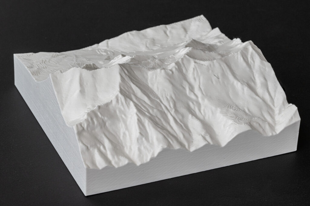
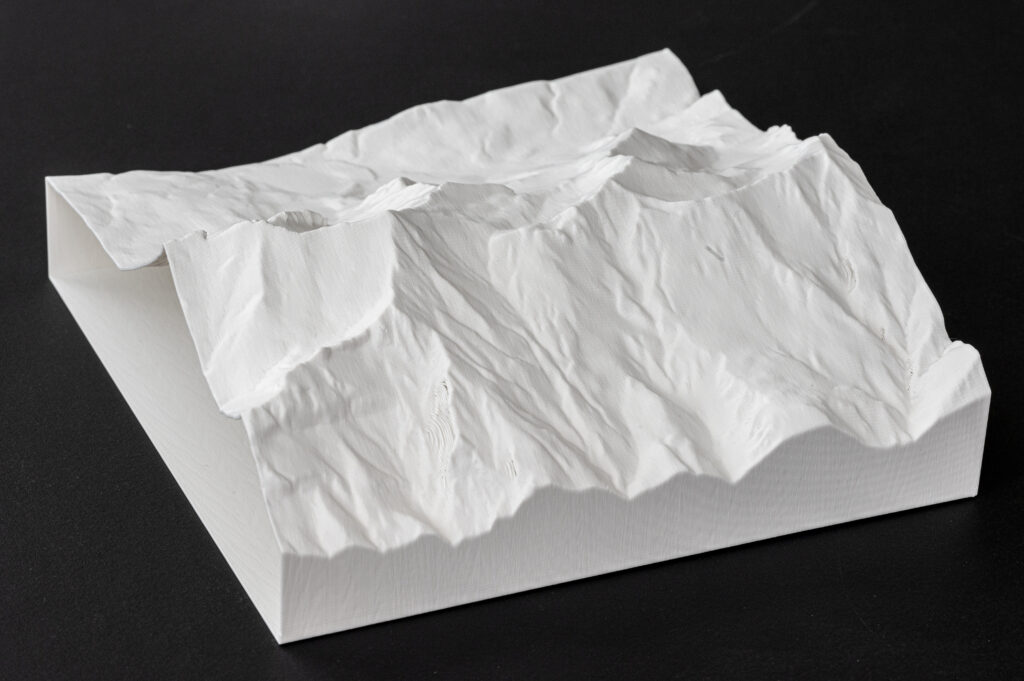
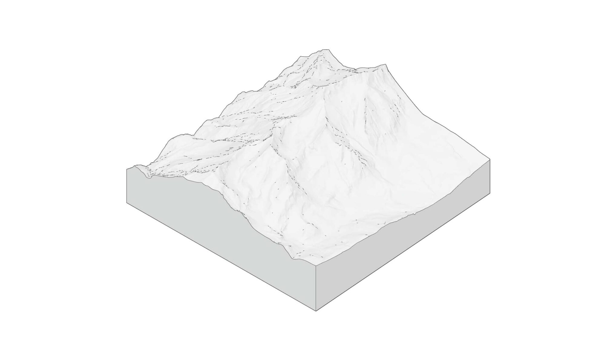
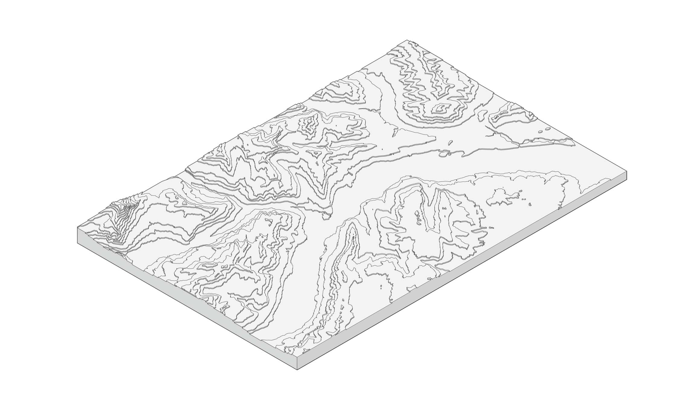
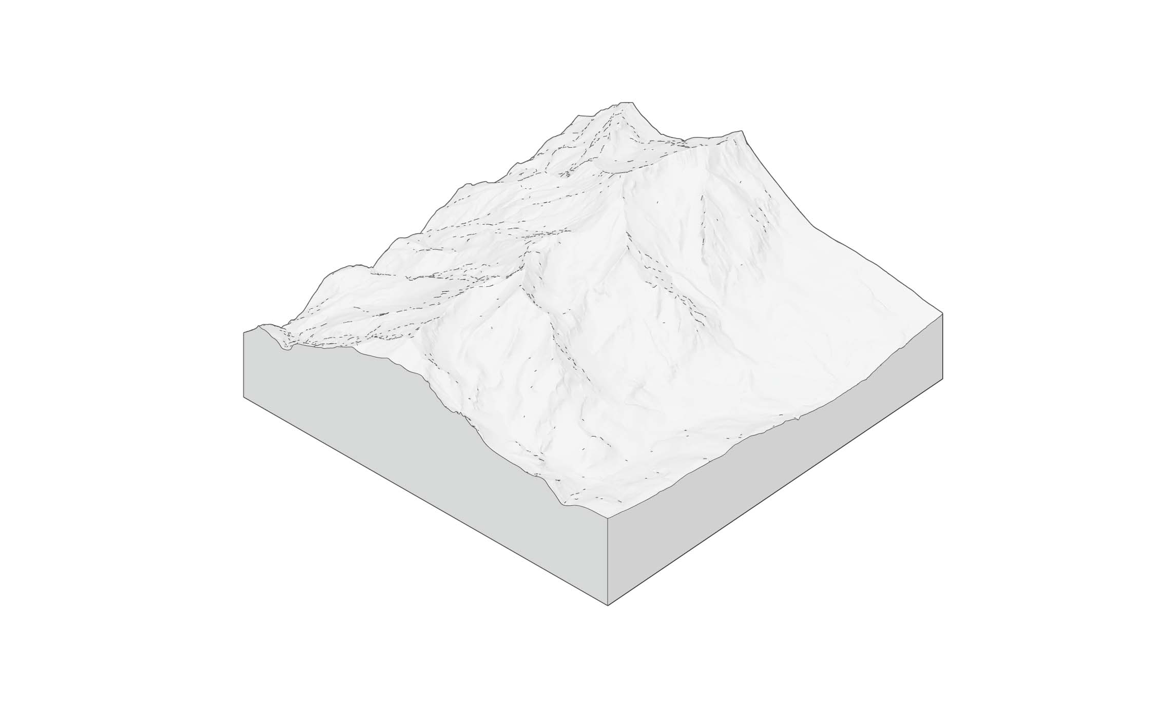
Landscape model 1:2000 - 350x350x130mm
FDM Printer ★★★★
Some complex 3-dimensional geometry with double curvature, which makes sense to 3D print.
The 3D model would have to be split in 4 pieces which could work. (Only 2 split lines)
The ‘spiral vase’ method could be used to reduce time
Zünd Cutter ★
The form is too organic and is made up of mostly double curved surfaces. Would be make very little sense to produce this on the Zünd.
Would only make sense to use the cut pieces to assist with another manual method in clay by creating templates or an internal armature.
Laser Cutter ★
The form is too organic and is made up of mostly double curved surfaces. Would be make very little sense to produce this on the laser.
Would only make sense to use the cut pieces to assist with another manual method in clay by creating templates or an internal armature.
Manual Method (Clay sculpting) ★★★
If perfect precision and accuracy isn’t of high importance, then this could be a very quick and effective solution.
Some templates or internal structure could be used to help by giving some more accuracy to the model.
A nice idea would be to produce the negative and pour in plaster for a more permanent model.
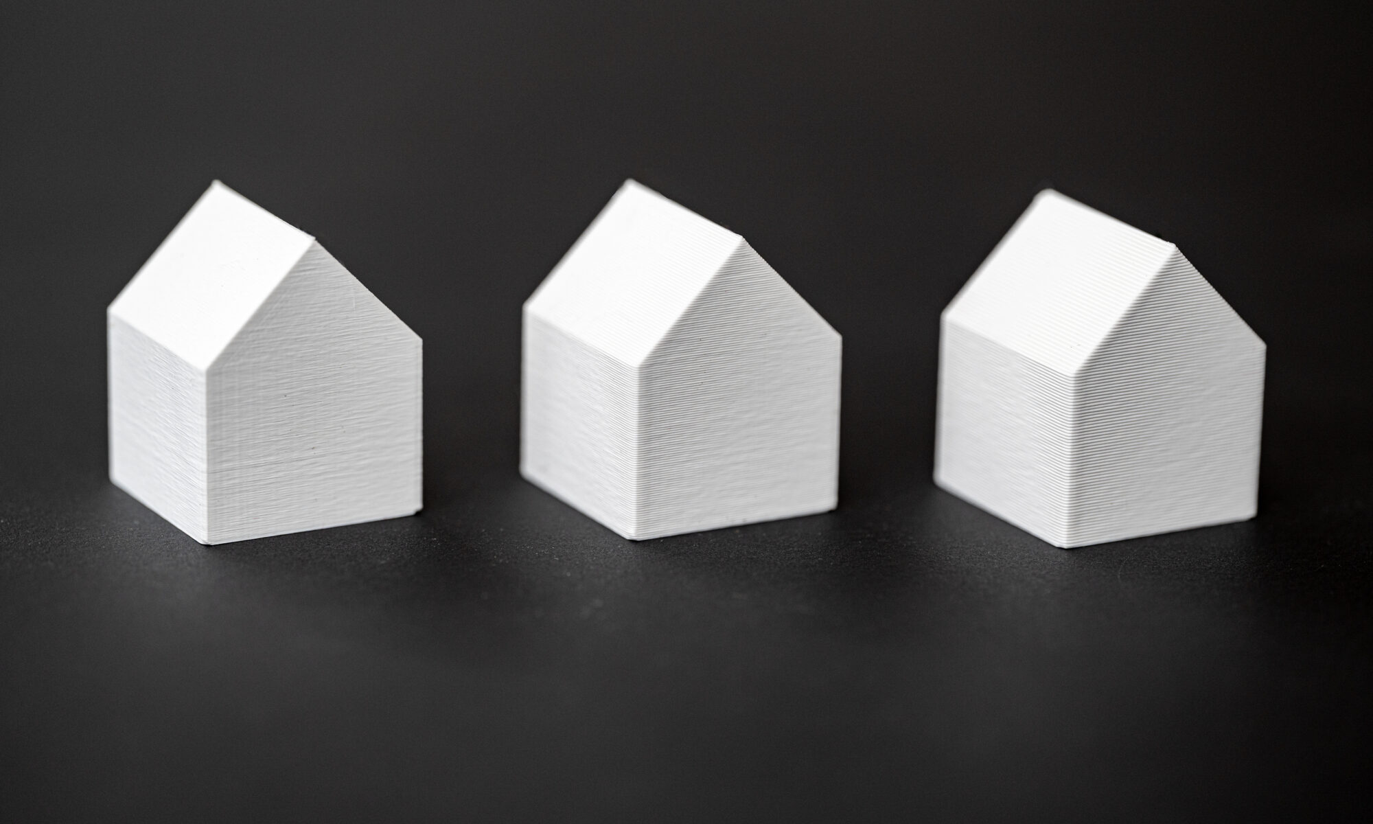
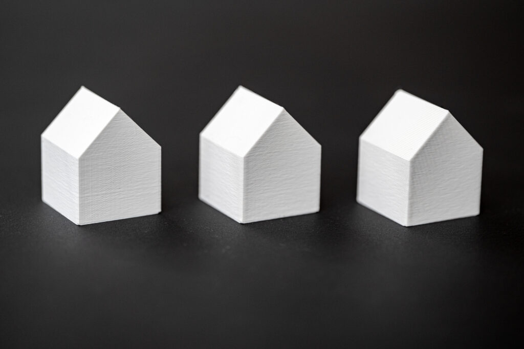
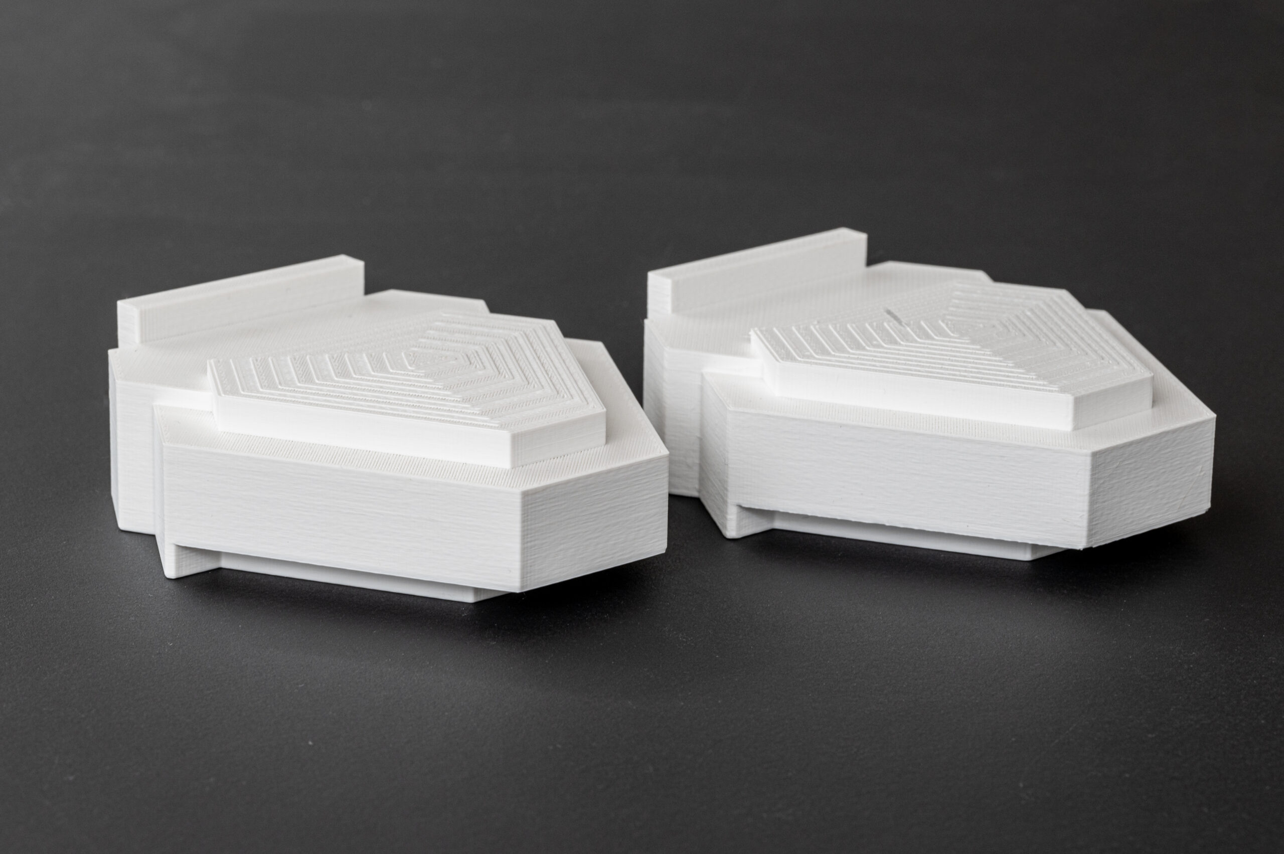
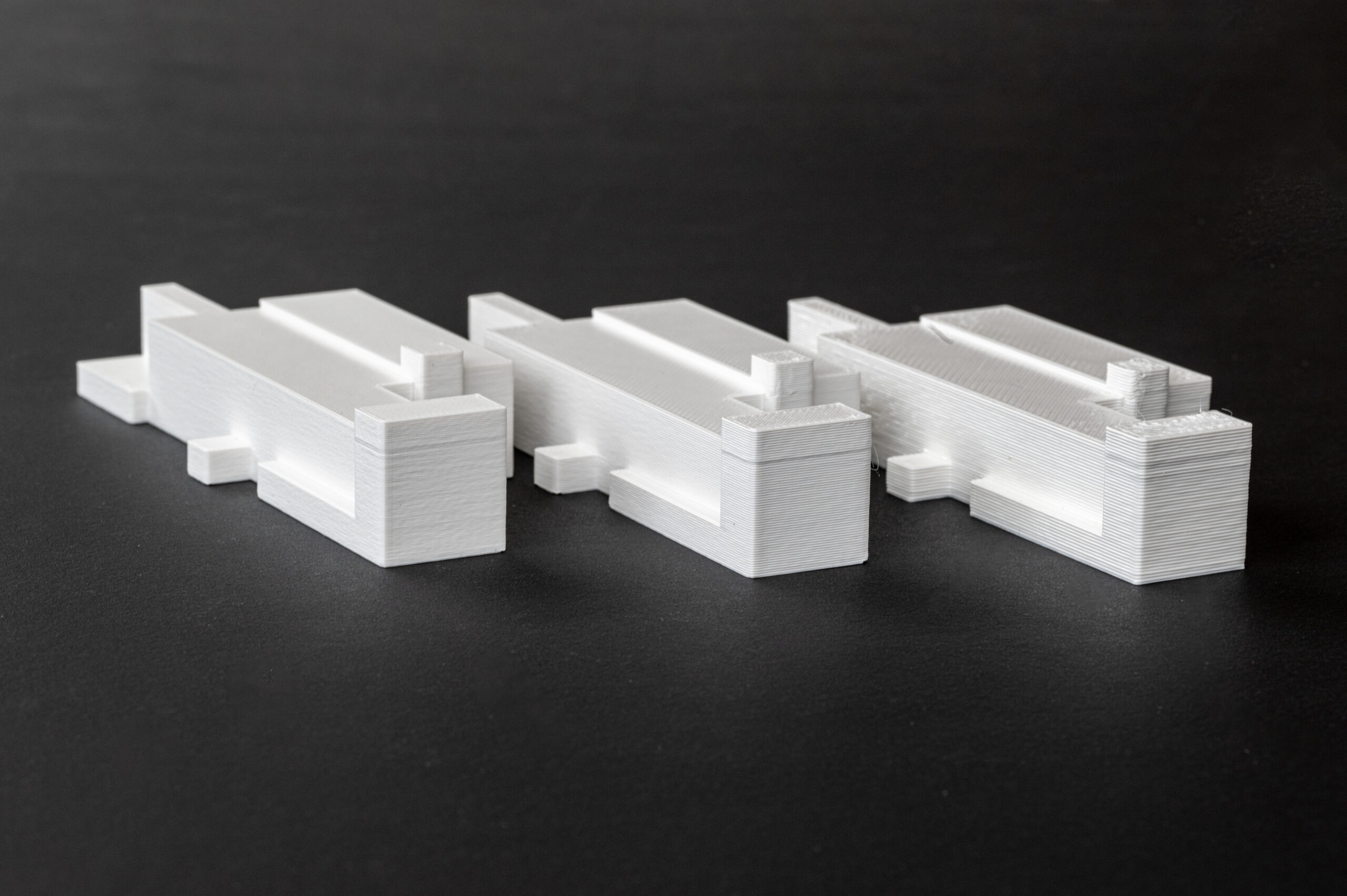
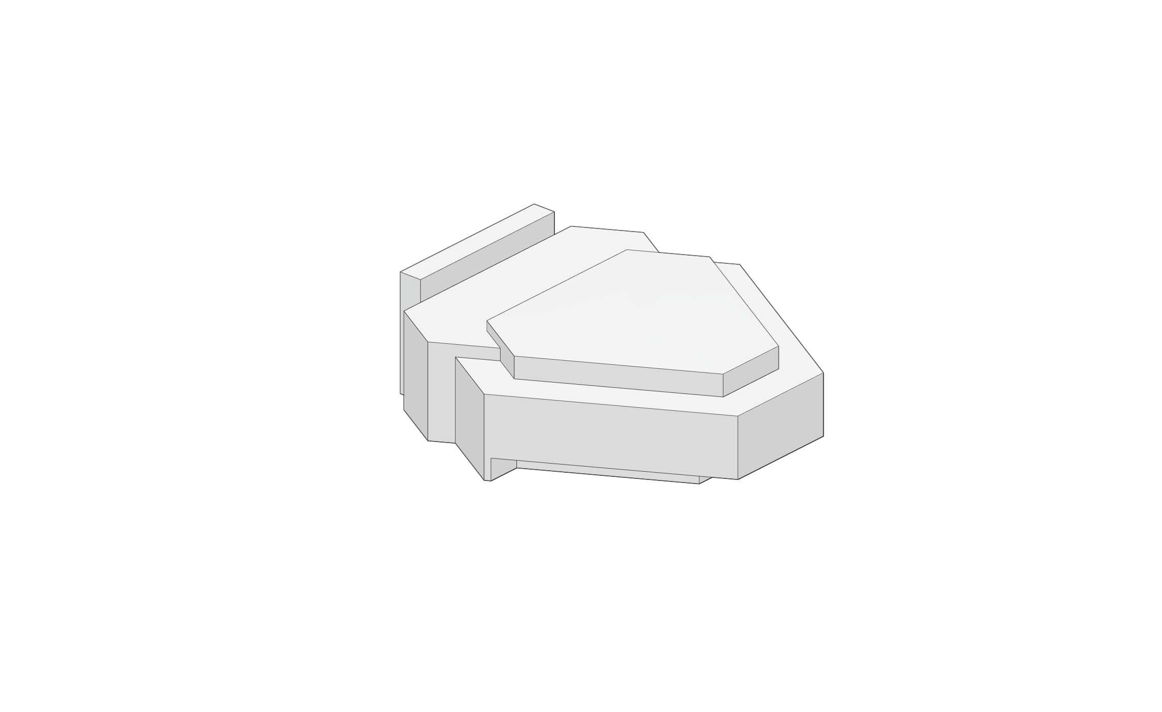
Small Context building 1:500 - 192x118x48mm
FDM printer ★★★★
FDM printers perform rather well producing small box like shapes
I would take a couple of hours to pint but a rather minimal amount of setup time
Could be clad in a thin material afterward or spray finished
Zund Cutter ★★
Would have to consider the construction method and redraw in 2D before cutting.
Requires some assembly
Laser Cutter ★★
Would have to consider the construction method and redraw in 2D before cutting.
Requires some assembly
Would have burnt edges
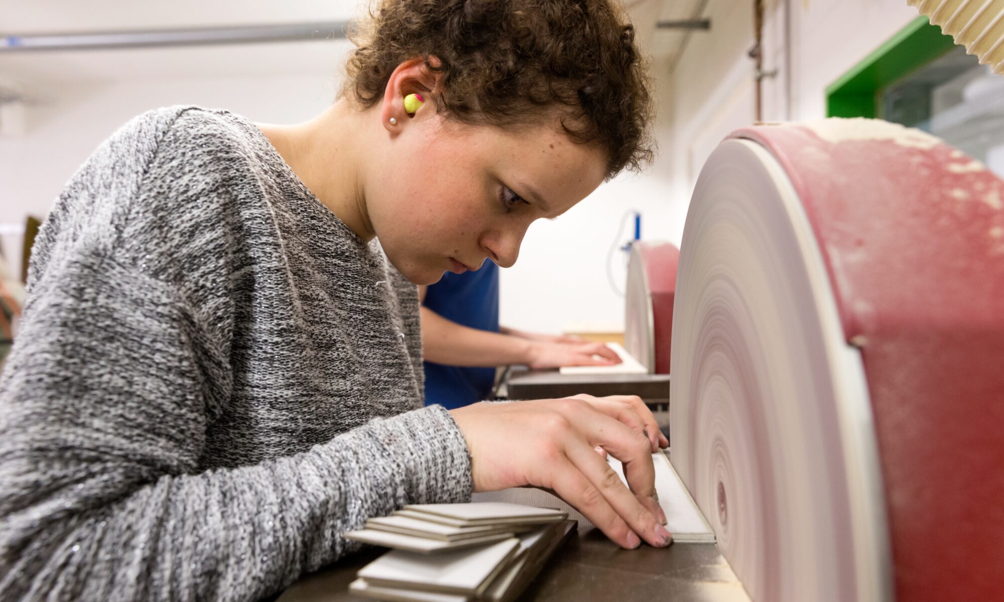
Manual method (Bandsaw and Disc sander) ★★★★
Most material options
Easier to sand the individual pieces before assembly. Would be able to achieve a very high-quality finish
Could be clad in paper or card afterwards.
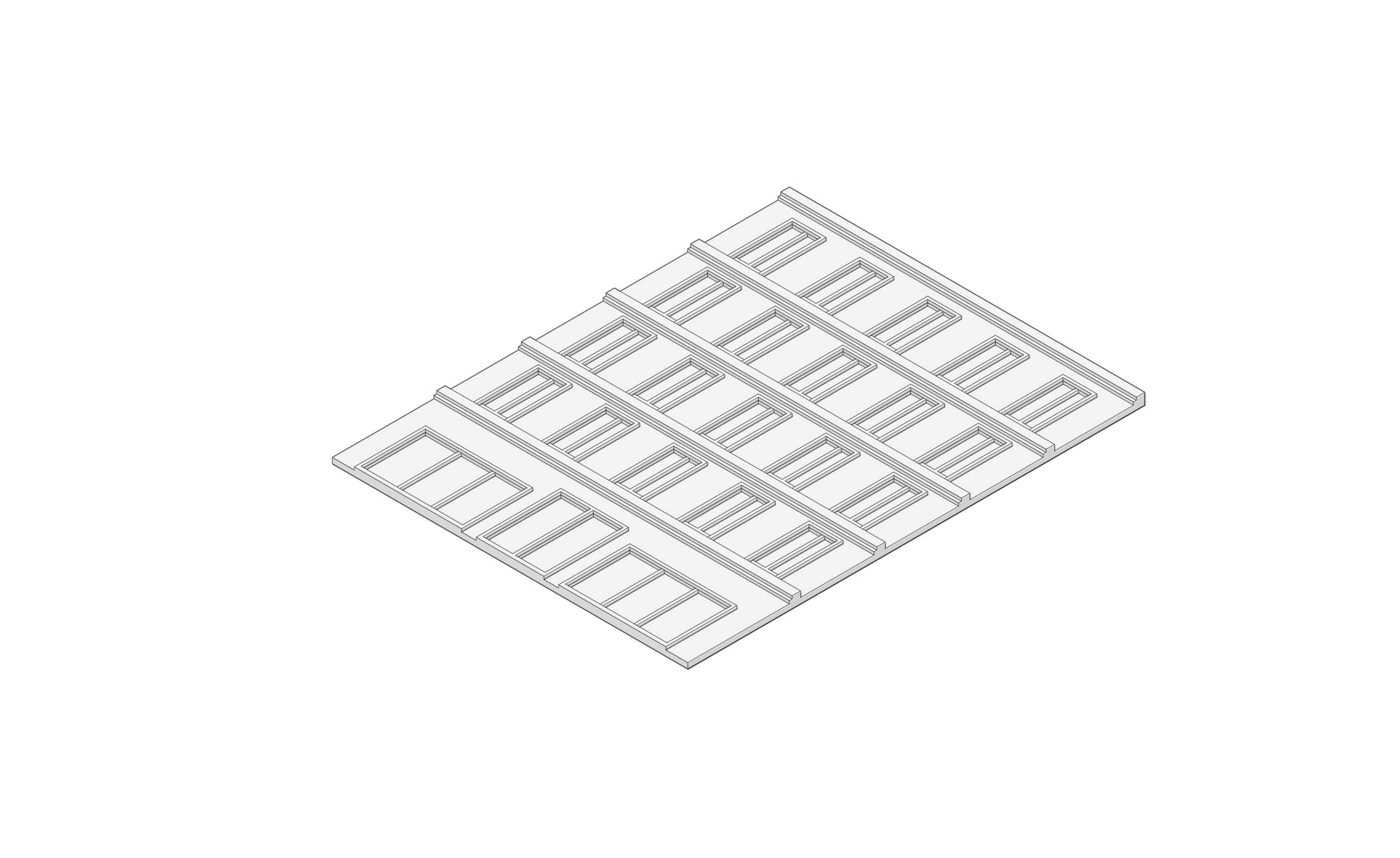
Facade 1:50 - 252x324x8mm
FDM-Printer ★
Not ideal for large flat pieces as it’s prone to warping.
Not the nicest quality finish for something of that size.
Too large for the printer to be printed in one piece.
Zünd Cutter ★★★★★
Would work very well as the elements could be broken down into layers and stacked.
Laser Cutter ★★★★★
Would work very well as the elements could be broken down into layers and stacked.
Manual method (cardboard and Knife) ★★
Would take rather a lot of time
If one has access to a digital cutter, it makes little sense to do this by hand and there are parts with internal cut-outs for the windows.
The strips under the windows however could quite easily be produced on the guillotine.
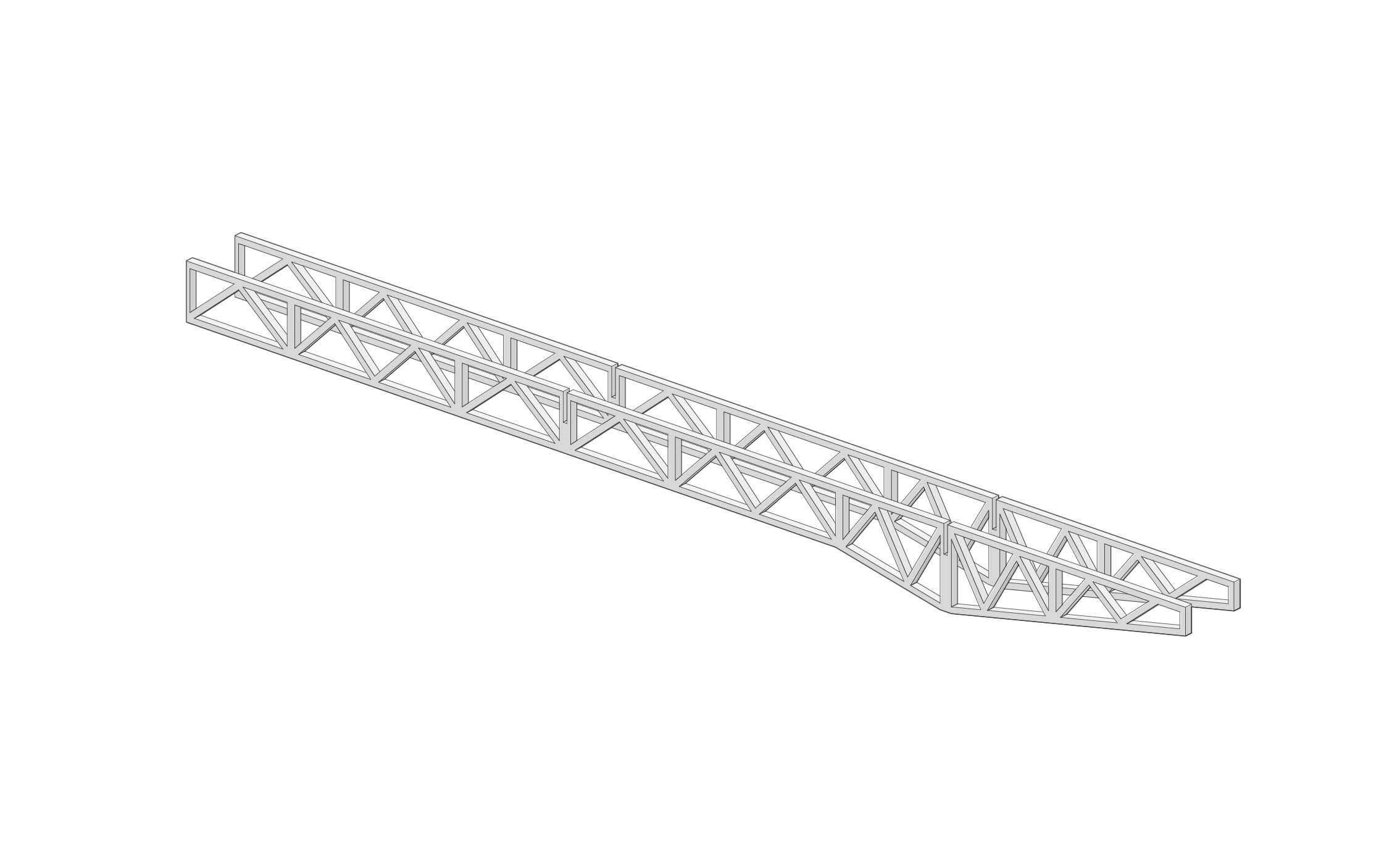
Structural truss 1:200 500 x 40 x 35mm
FDM printer ★★
Structure not too suitable for FDM printing as the profiles are rather thin. Would work for SLS or SLA but would be very expensive to produce at this scale.
Too large to fit on the 3d printers at the Raplab
As these parts could easily be produced on a digital cutter there is no reason to print these
Zund Cutter ★★
Would maybe struggle a bit with the small details
Would slightly overcut in the corners making them very weak
Laser Cutter ★★★★★
The laser would have no problem replicating something with these intricacies
There would be some assembly required
Manual method ★★ (wooden sticks)
Would take a lot of time and effort to produce something rather fragile.
