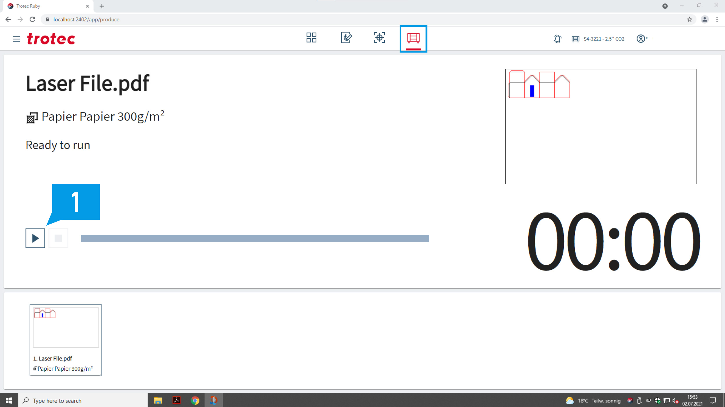
The machine user must stay with the machine for the duration of the cutting time.
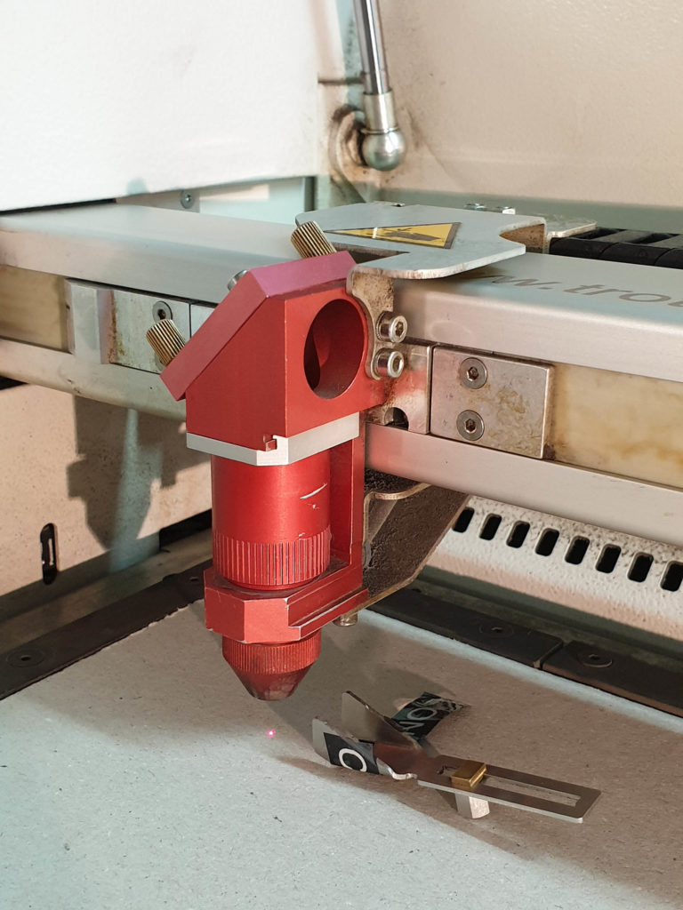
If there are flames above the sheet material, pause the job and notify a staff member.
A small amount of smoke in the machine cabinet if normal. However is the smoke seems to build up inside the cabinet pause the machine and notify a staff member.
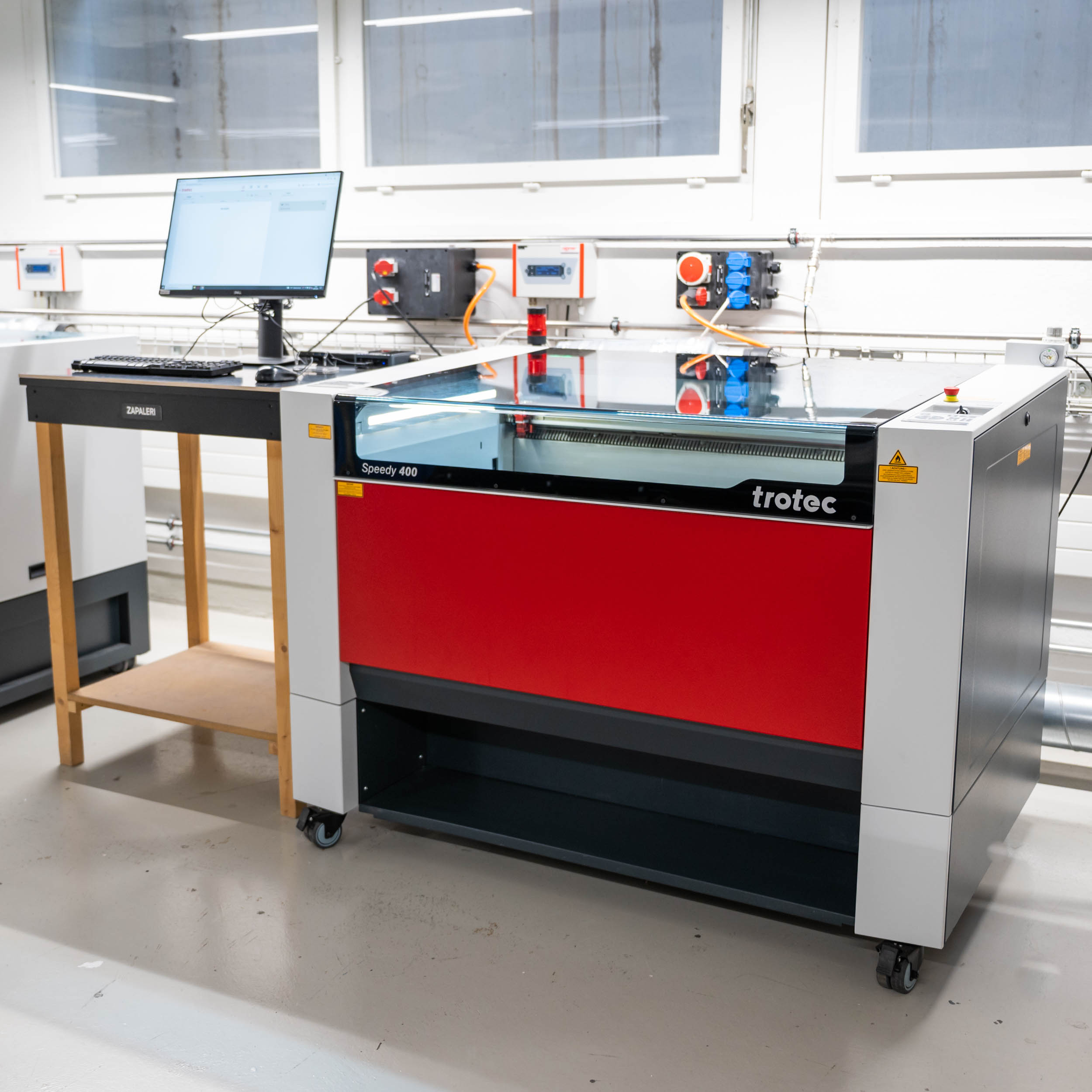
Cost: 20.- / h (starts from login time!)
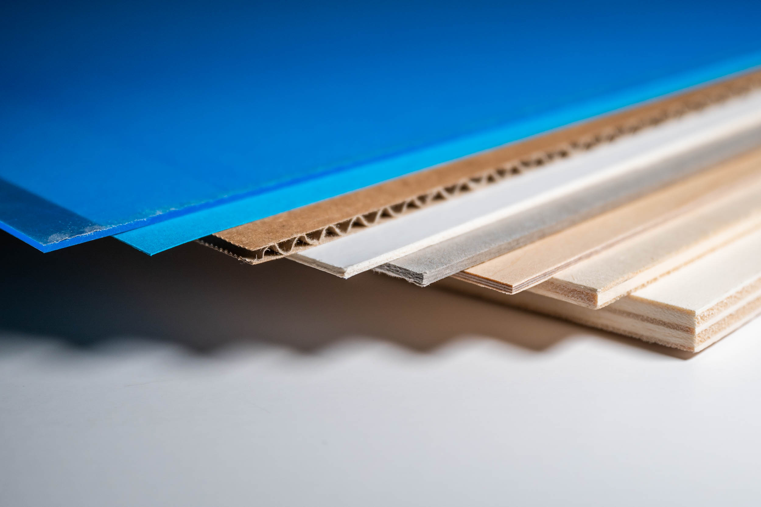
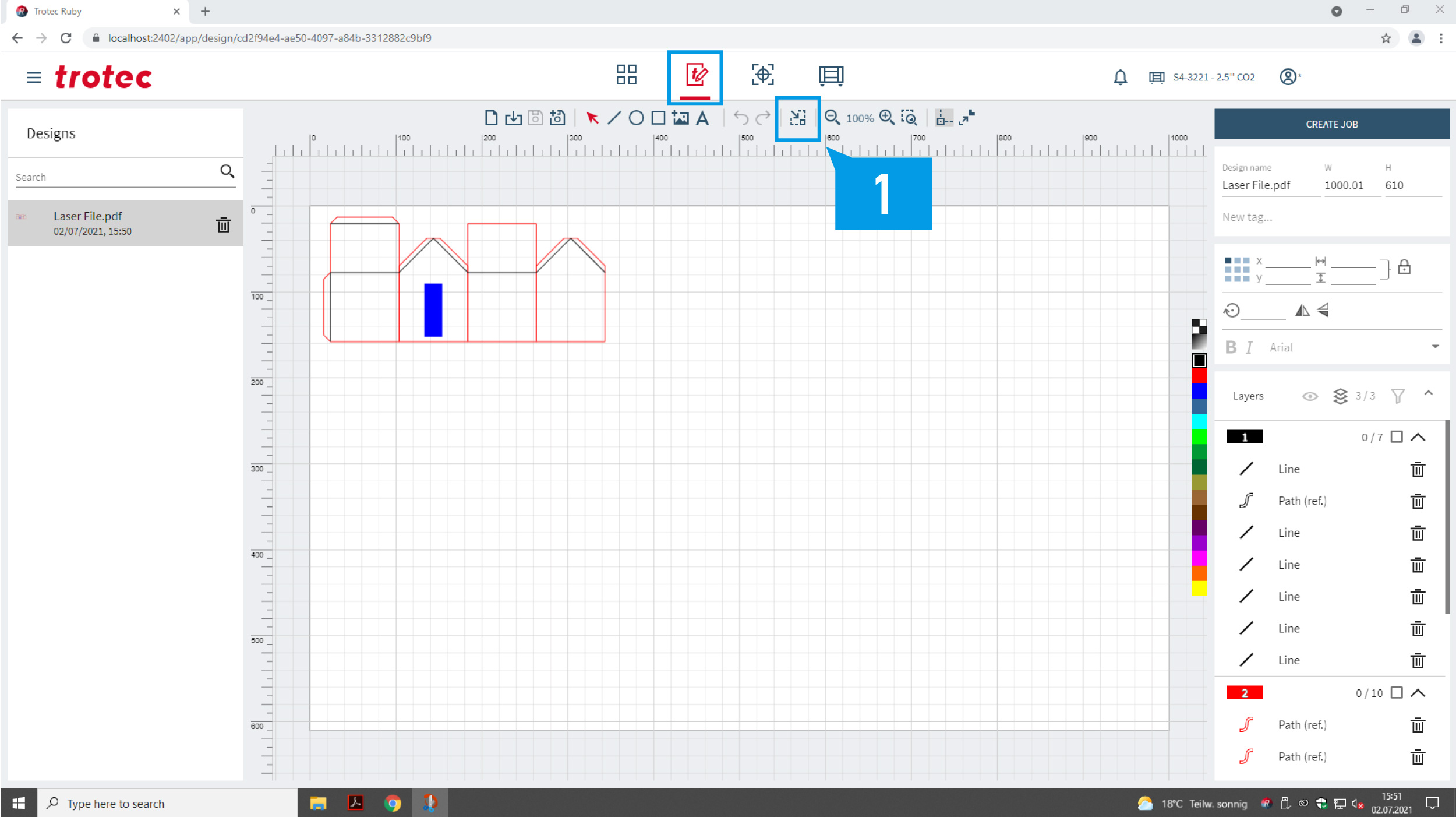
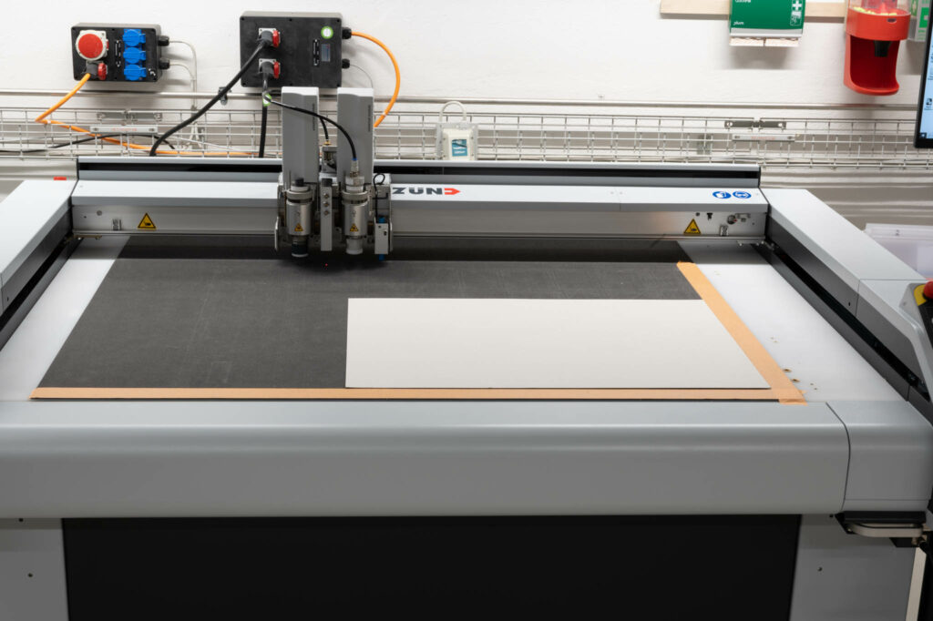
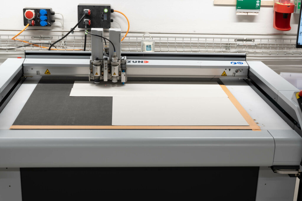
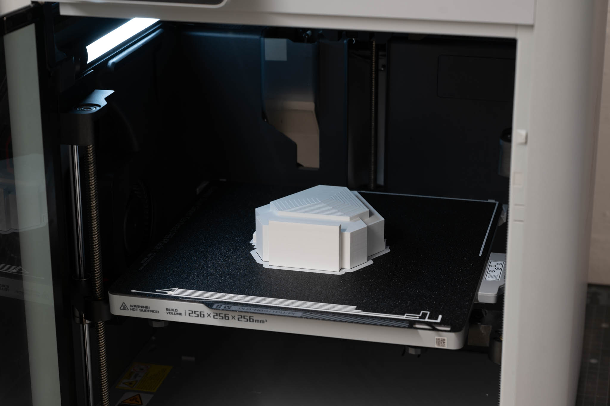
Area: 1000mm x 600mm
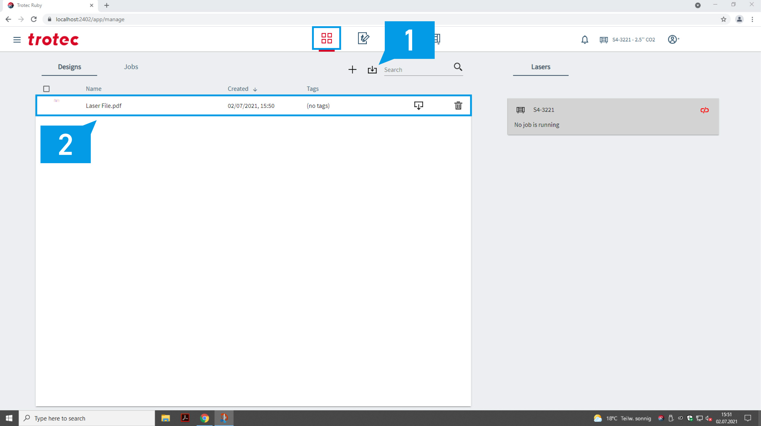
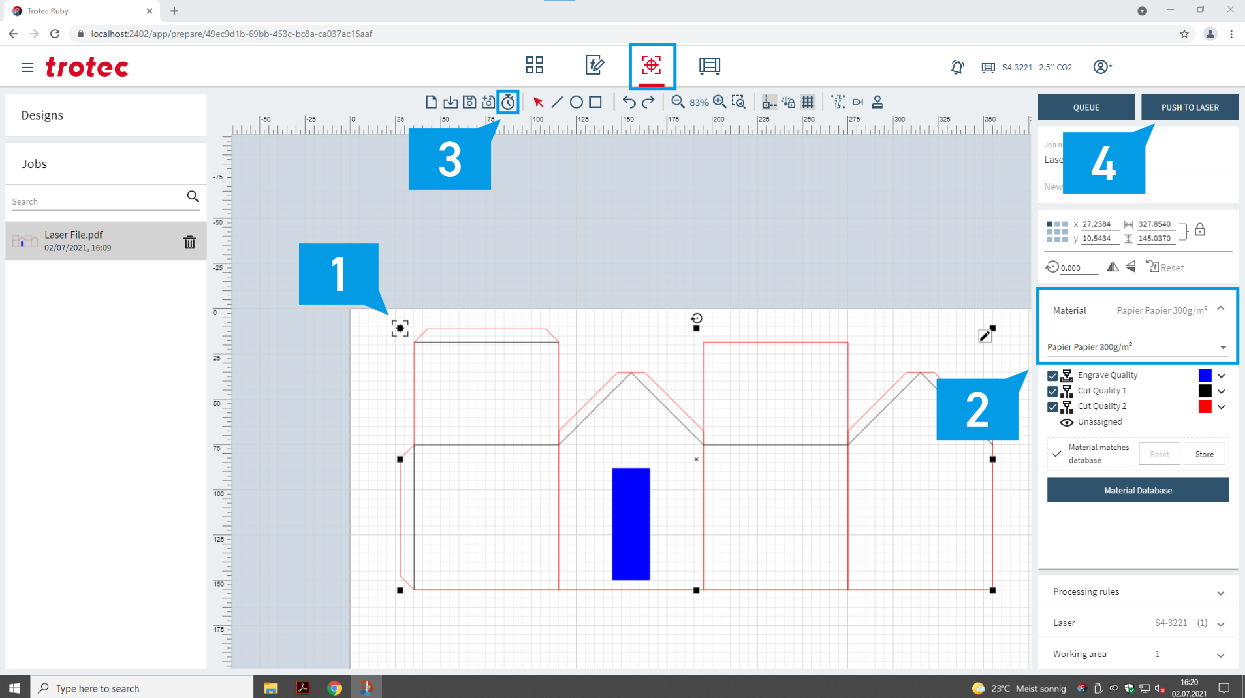
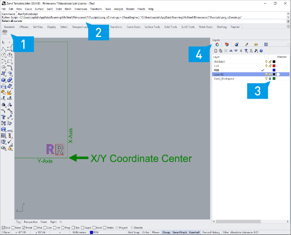
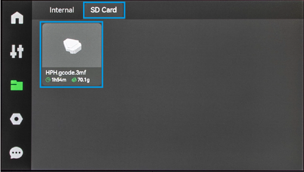
File: PDF, RGB colors, vector-based, no groups
Colors: