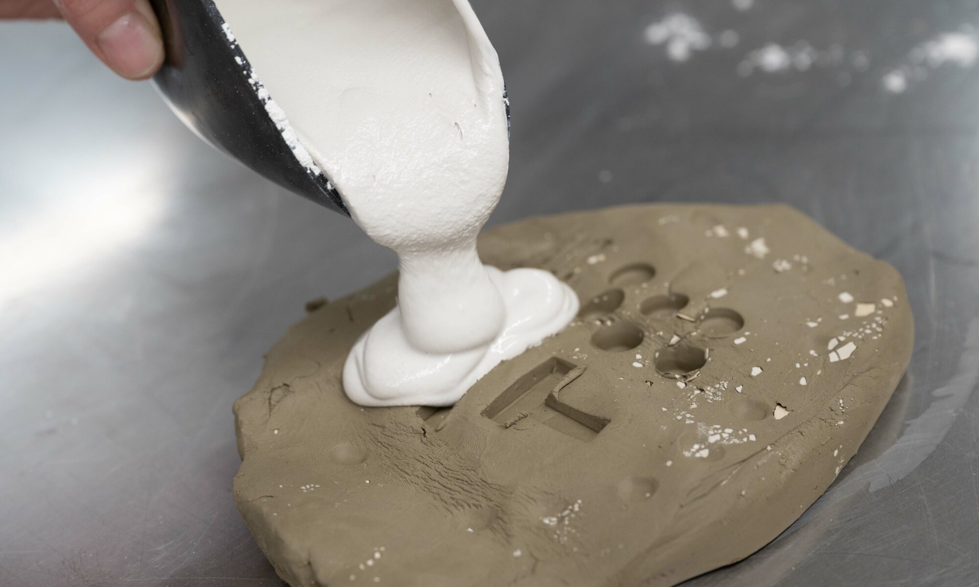
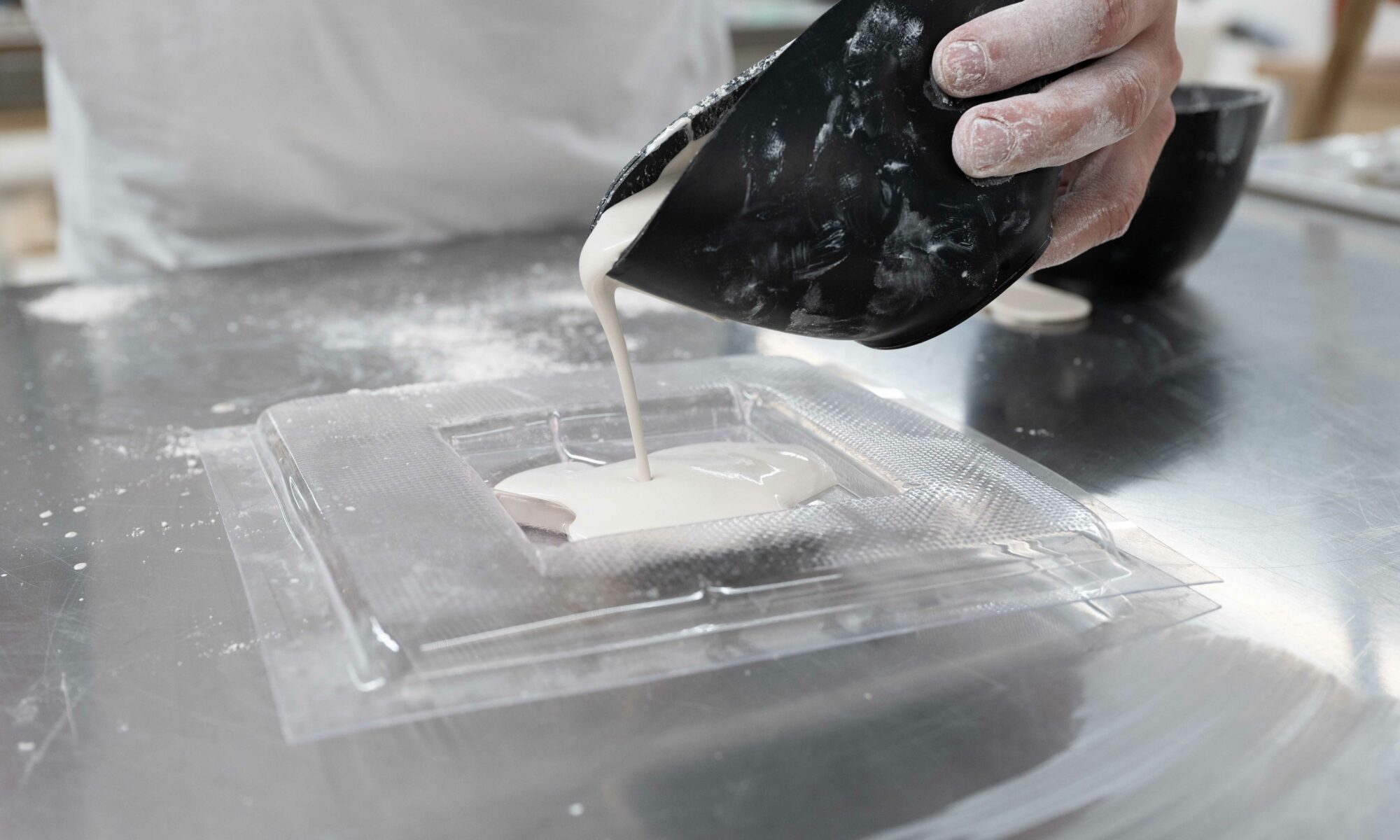
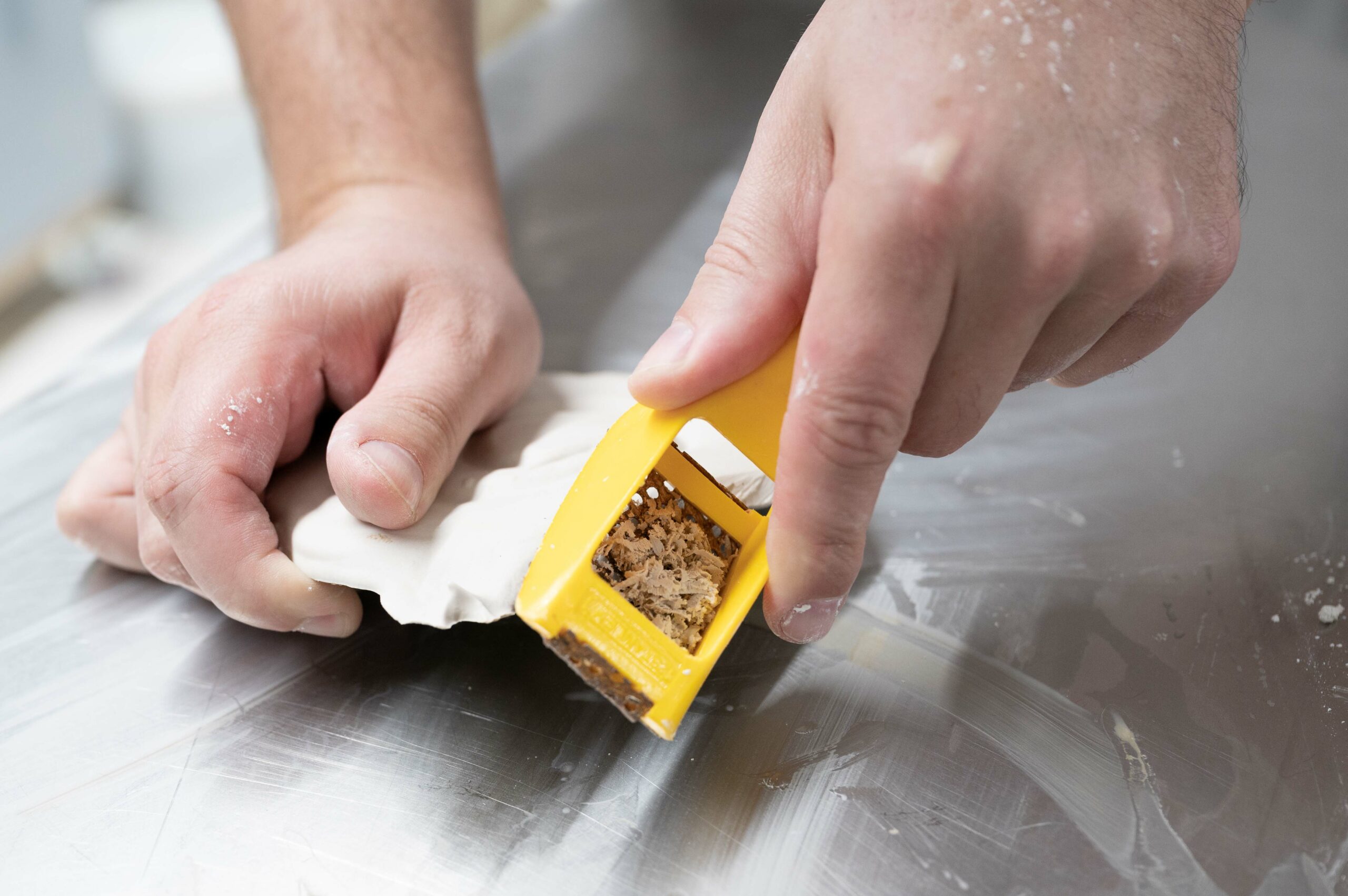
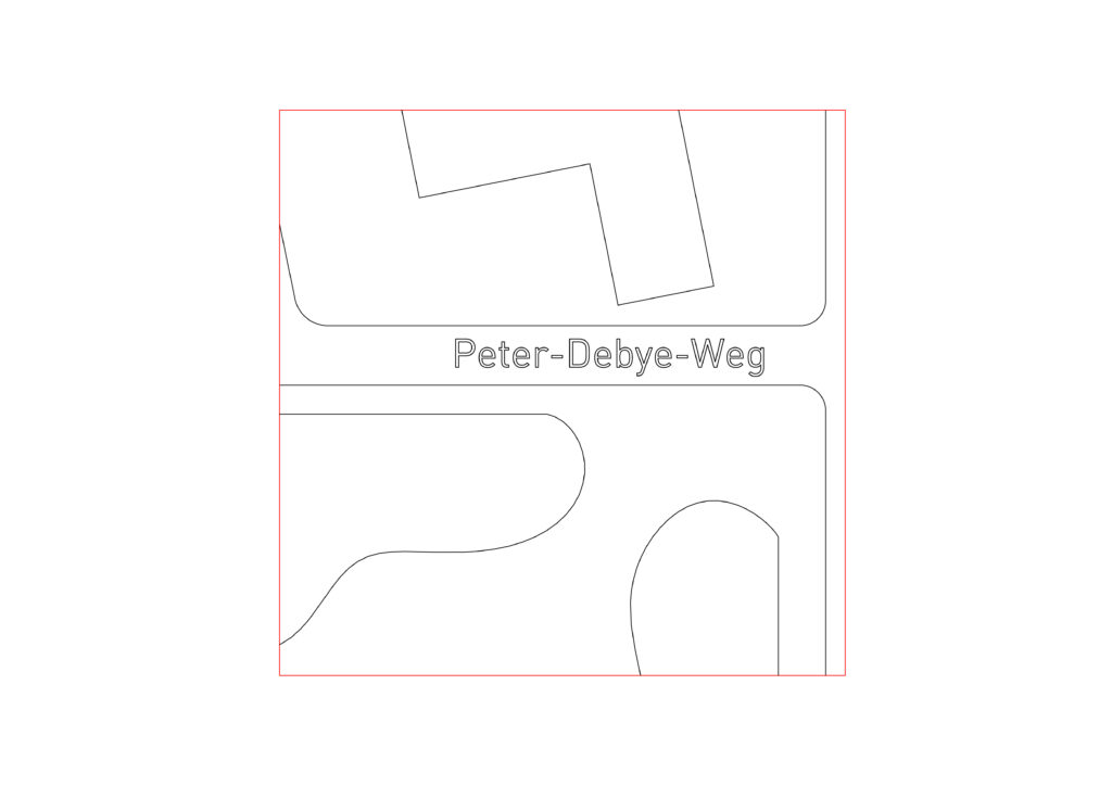
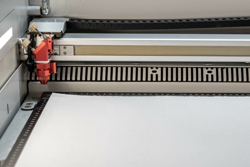
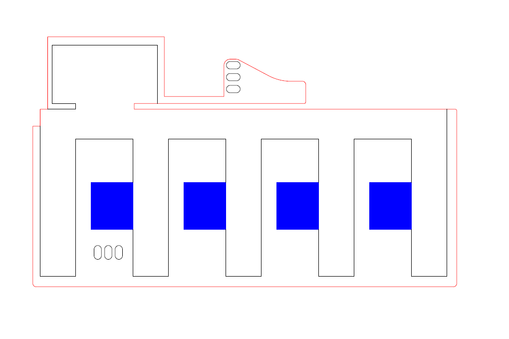
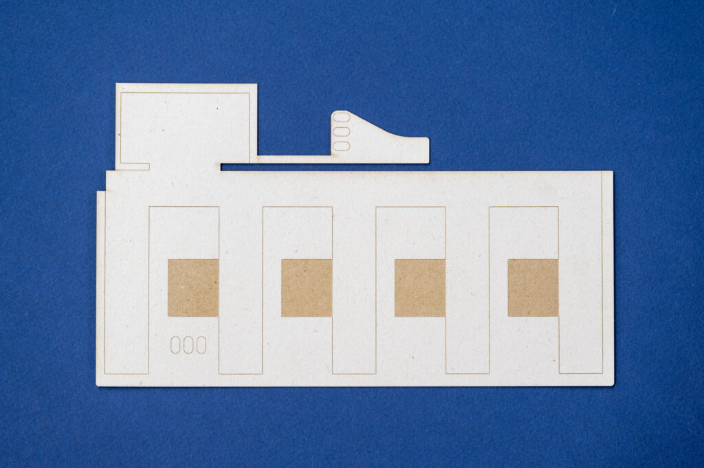
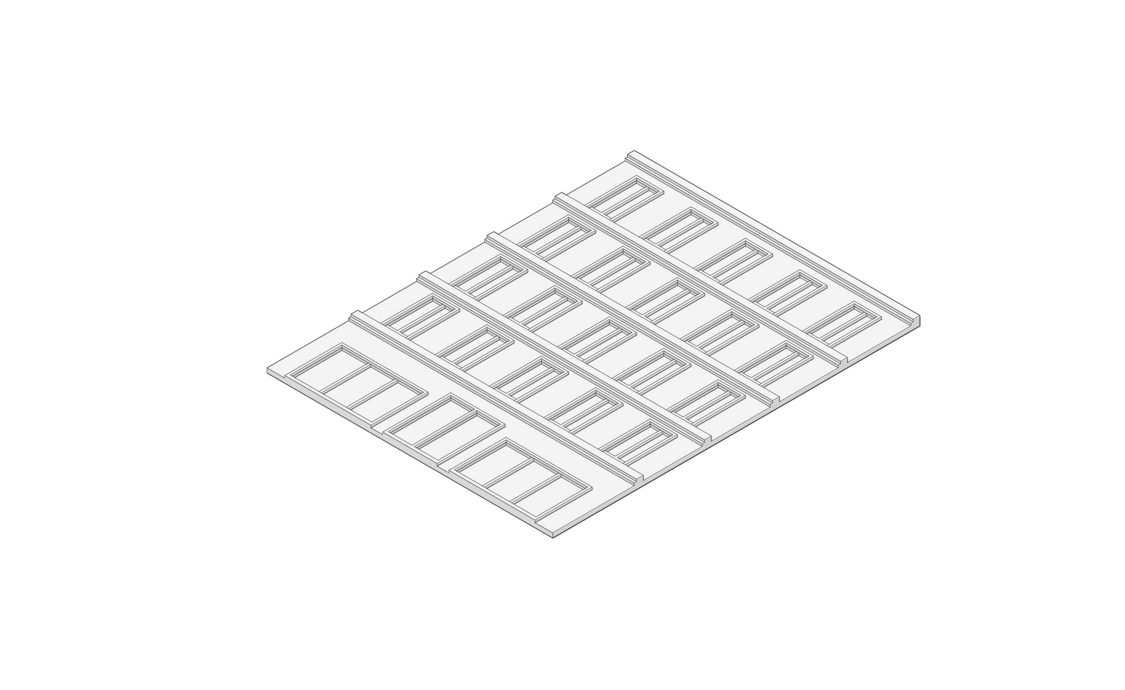
1 — Building the mold
The significance of mold-making can not be overstated. Typically, a substantial amount of time and work is spent to prepare the molds for casting plaster. Making the mold is the stage that, besides properly mixing the plaster itself, determines how successful your outcome will be.
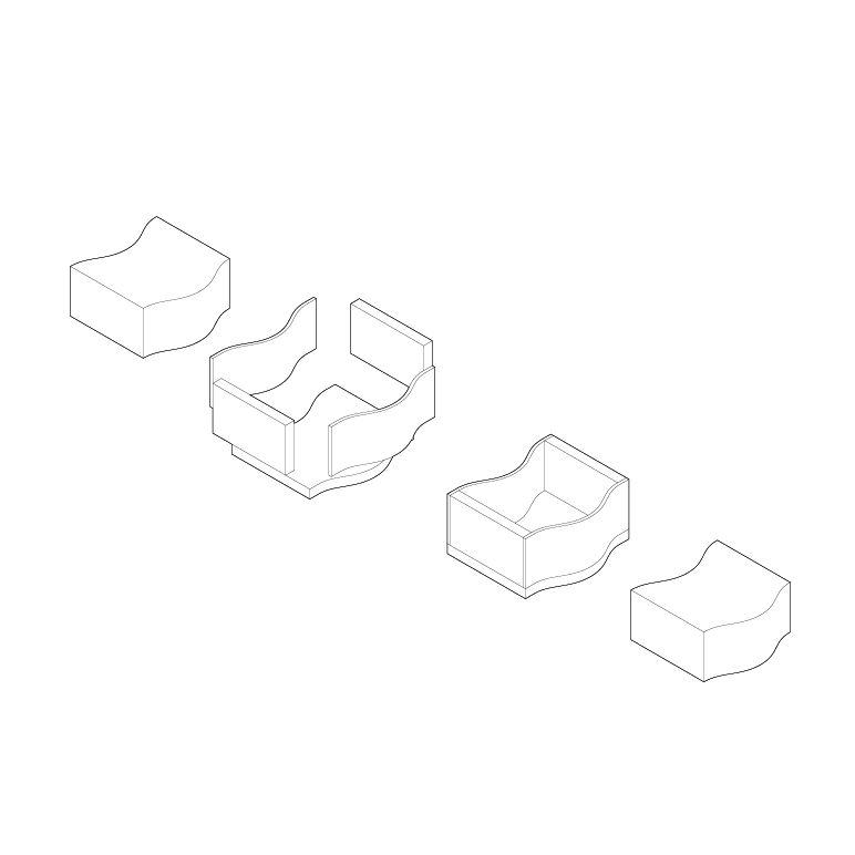
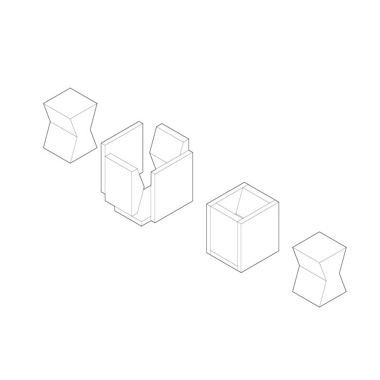
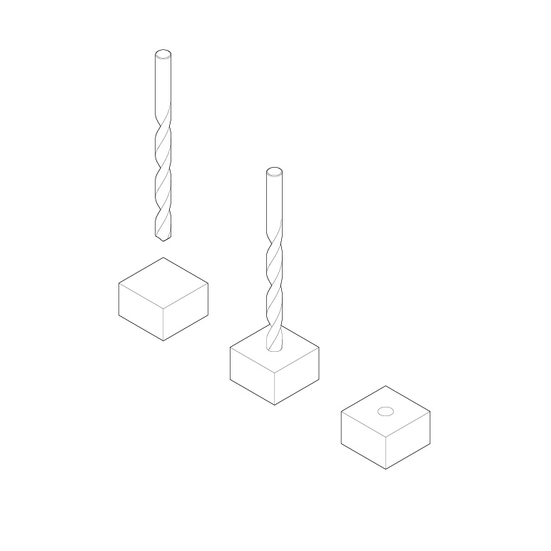
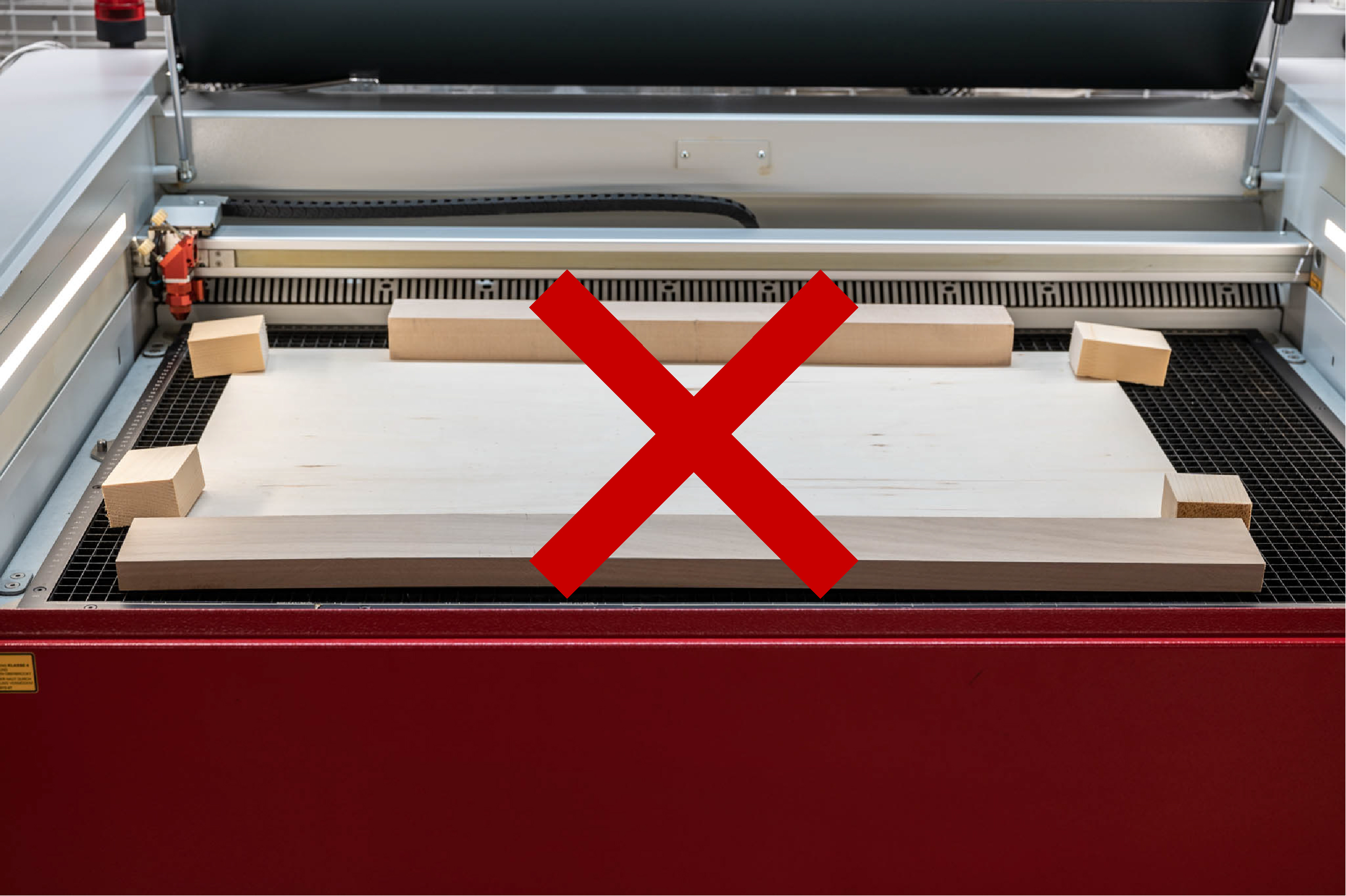
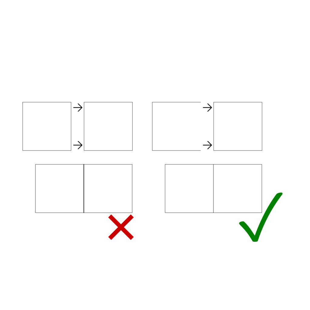
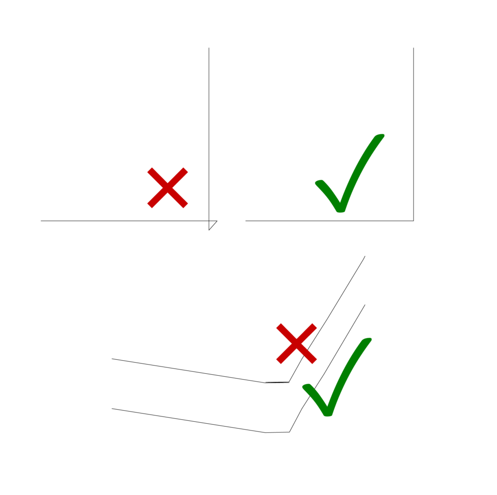
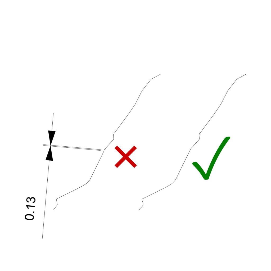
Ensure your molds are constructed to be watertight, sealed, and easy to disassemble. There are various methods and tricks to good mold making; some of them are outlined in the following post:
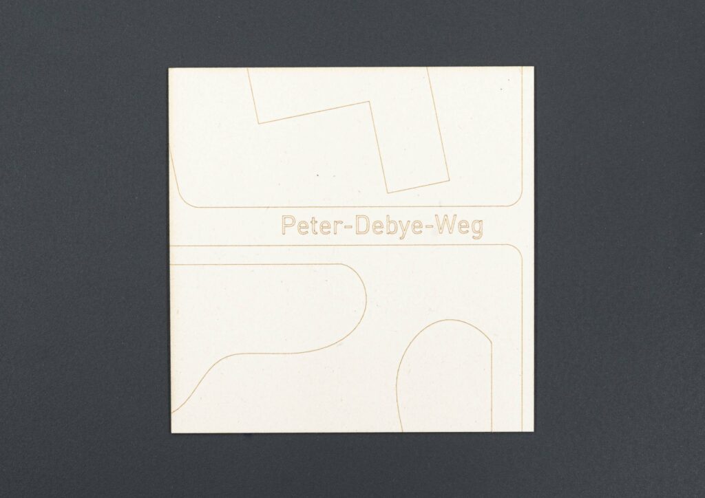
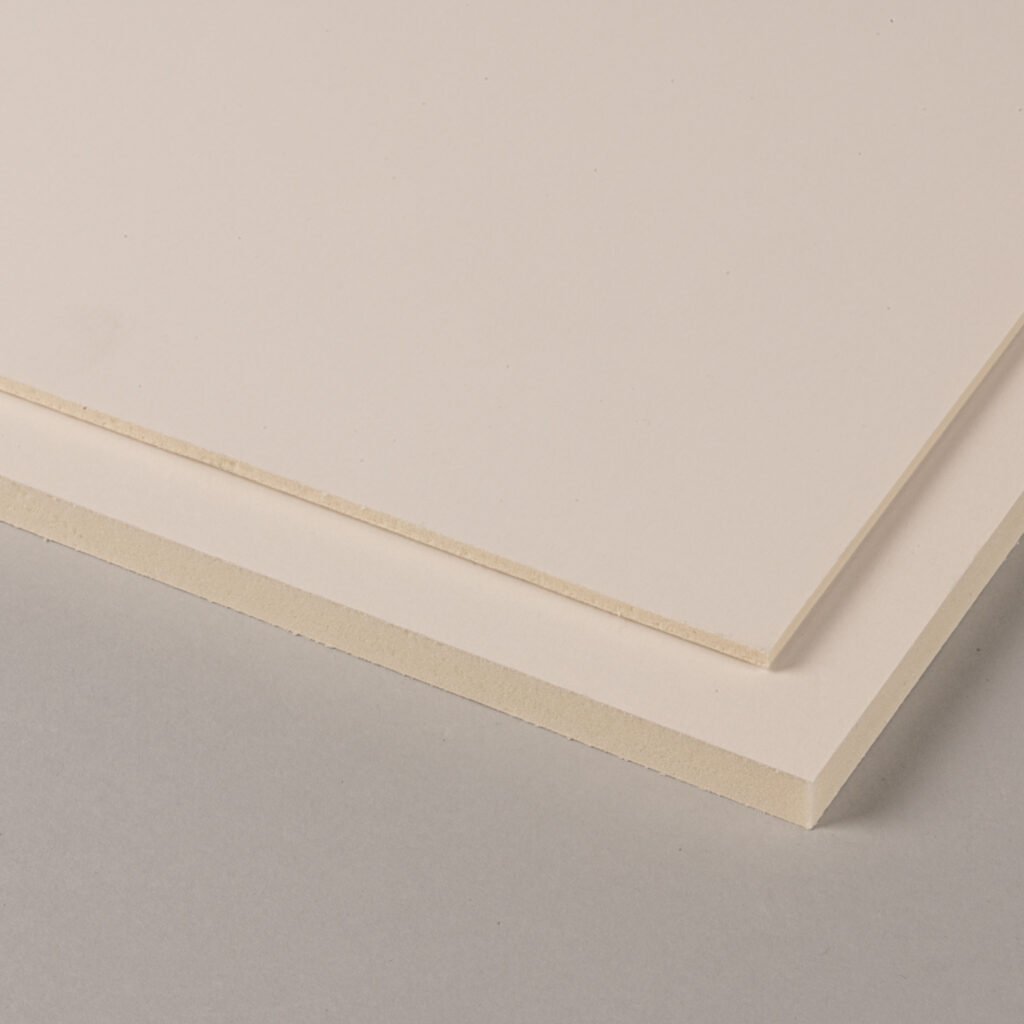
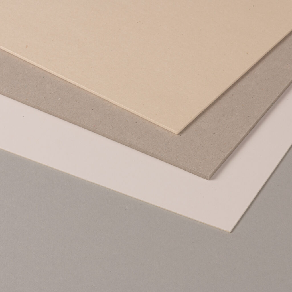
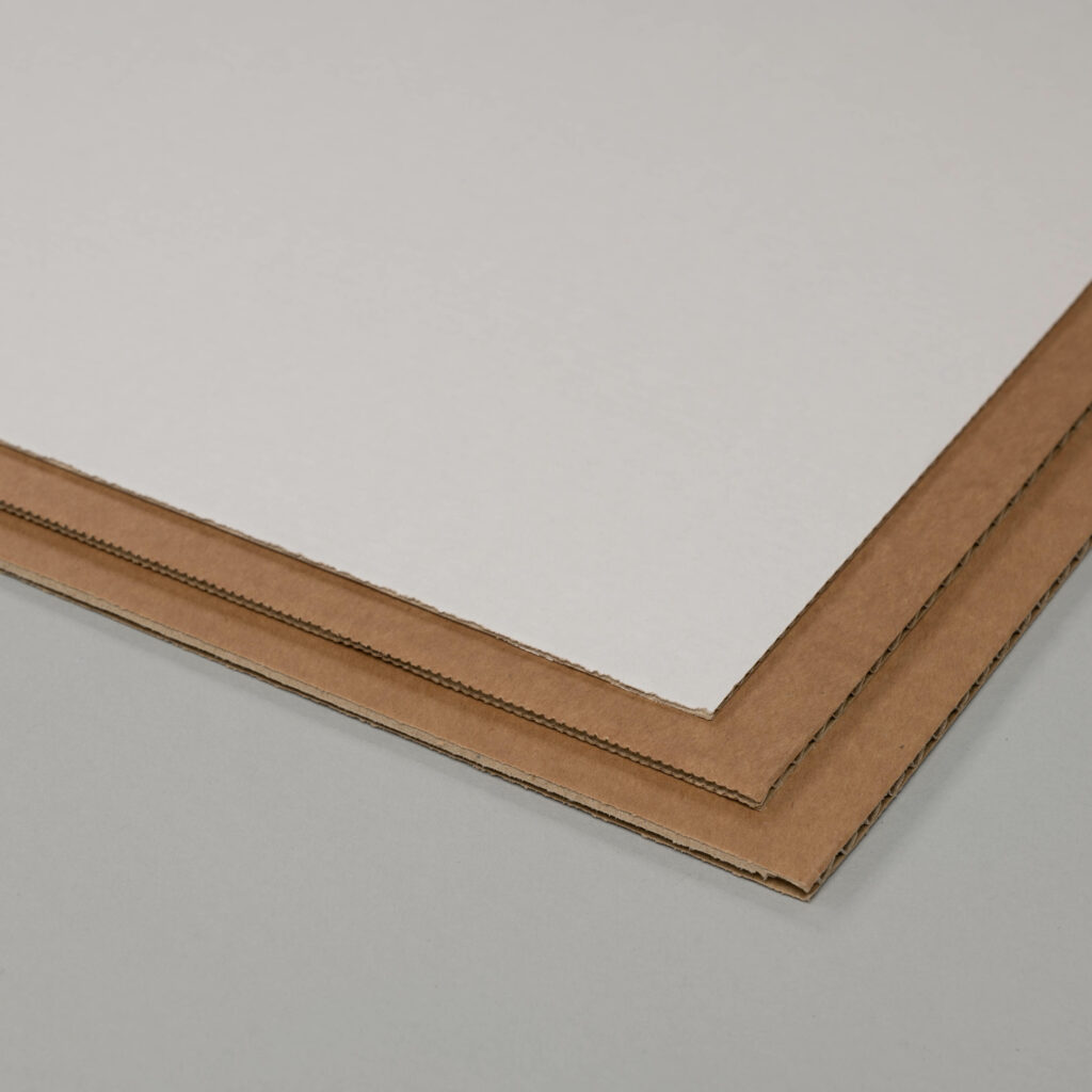
Simple molds for plaster and concrete