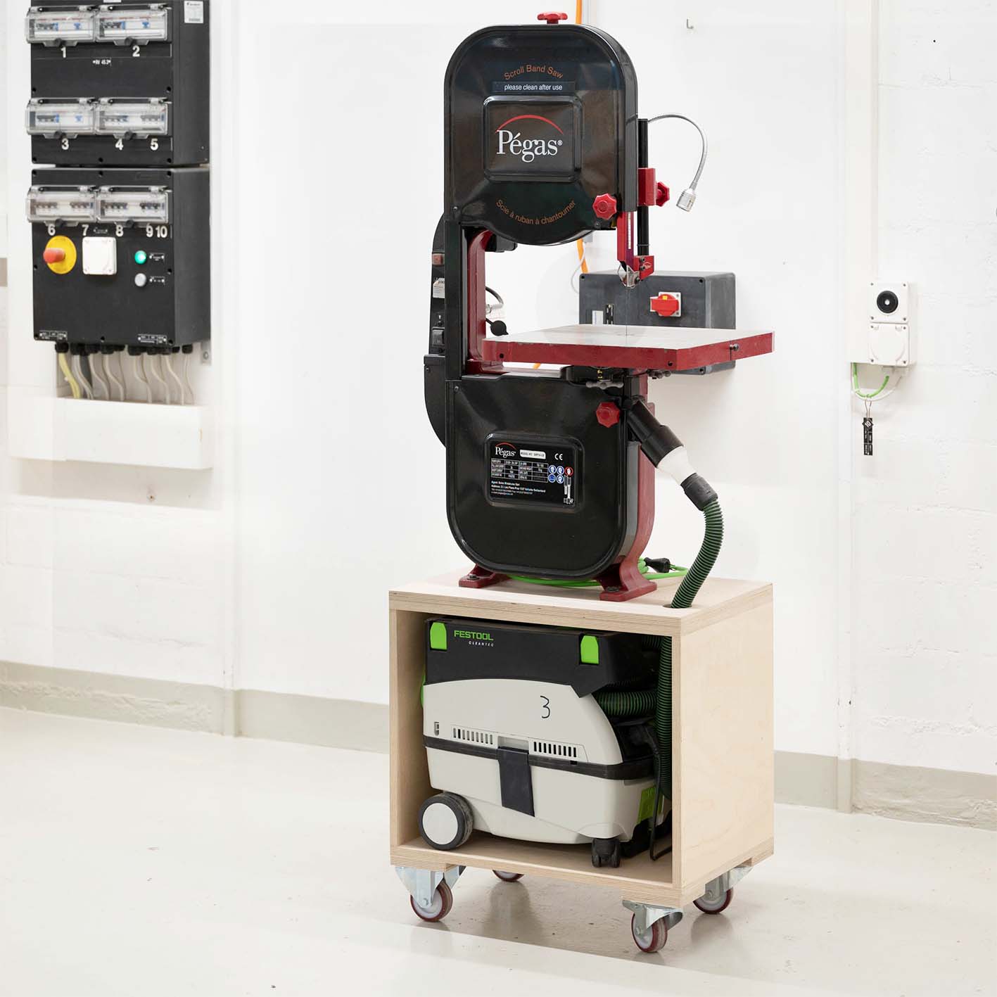
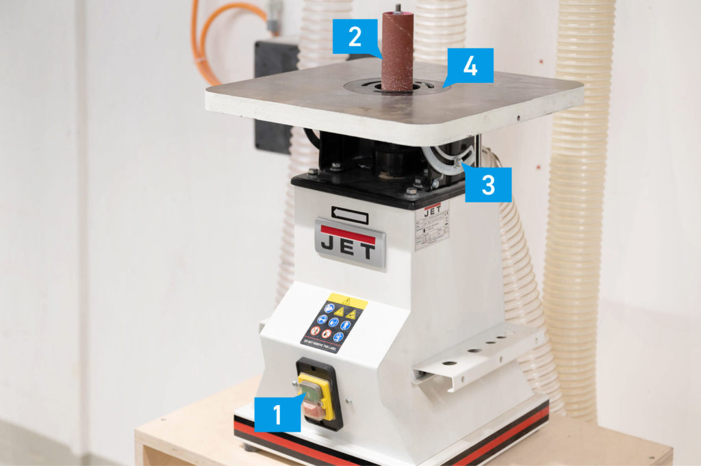
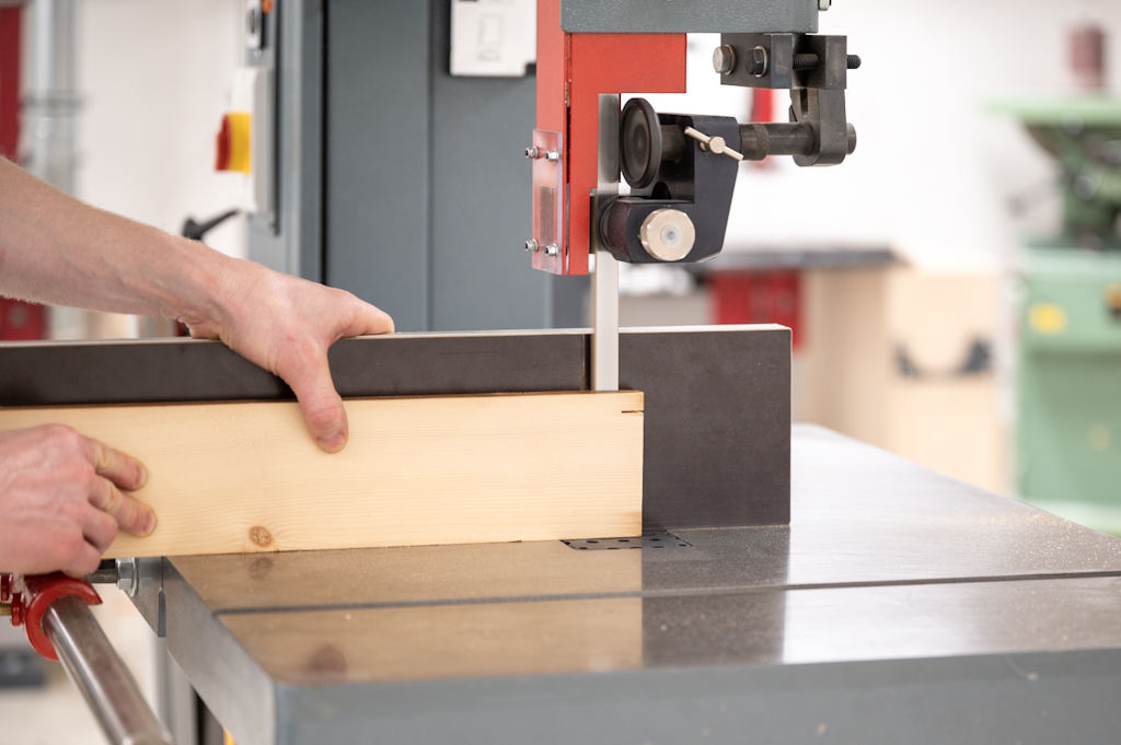
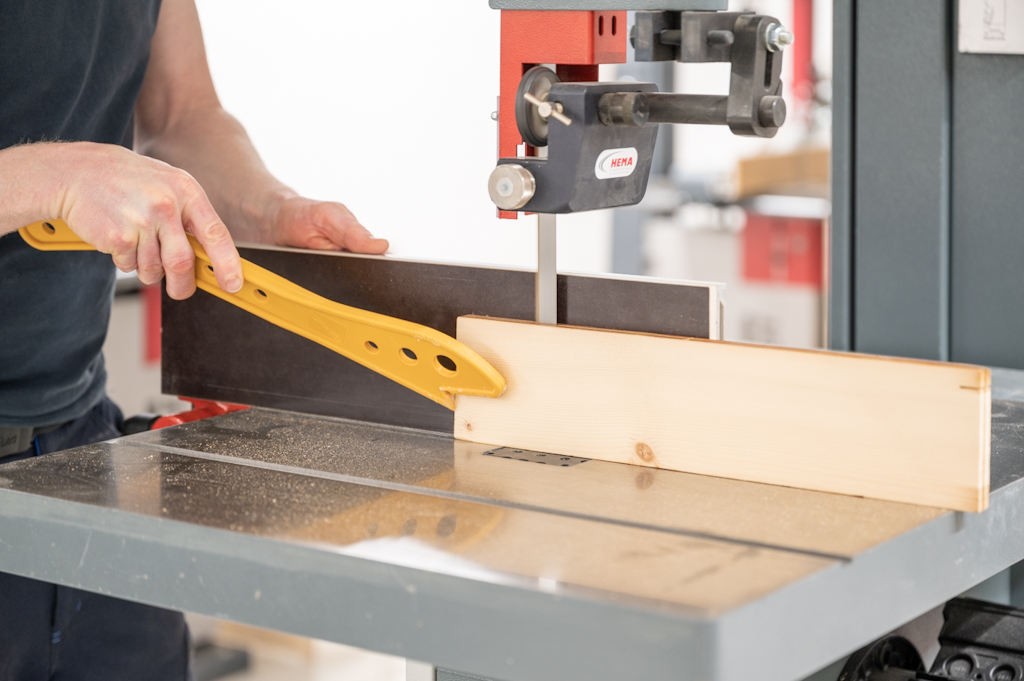
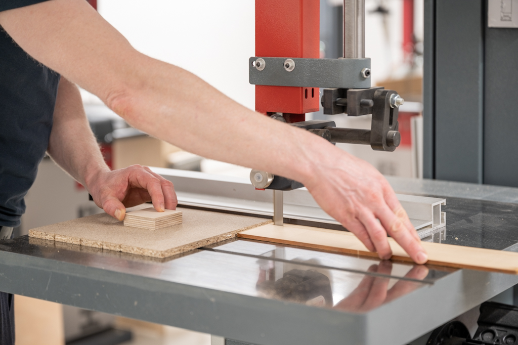
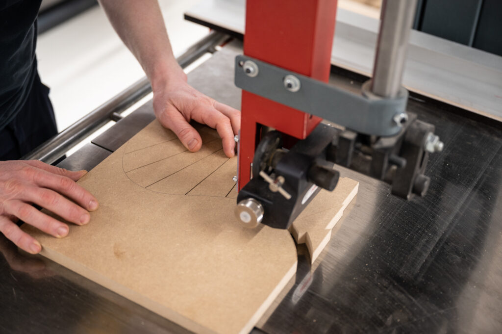
Scroll Band Saw

Scroll Band Saw

Introduction

Toy and model makers commonly use Scroll Bandsaws for workpieces requiring intricate curves and detail. 
The scroll bandsaw can cut finer details than the bandsaw and thicker stock than the scroll saw; this ability makes it an ideal machine for workpieces that require fine details in basswood or PU foam.
At the Raplab, the saw is used most commonly instead of a hot wire cutter to cut styrofoam (EPS and XPS) for formwork. 

Scroll Bandsaw Overview


#1 Power switch
#2 Wheel for adjusting guide hight
#3 Guide assembly
#4 Light
#5 Light power switch
#6 Guide post
#7 Guide post lock

Preparation

Before you turn on the machine, set the guide assembly to the correct height. It should be no more than 10mm above the workpiece. As the picture shows, the scroll band saw can cut materials up to 100mm in thickness. This ability depends on the hardness of the material – remember that a piece of oak (high density and hard) is different from basswood or styrofoam (low density and soft)!

The scroll bandsaw works best for intricate curves and detail work; resawing stock and straight cuts is a task for the bandsaw and should not be attempted with the fine blade of the scroll bandsaw.

How To

Part of the safe working procedures of every woodworking machine is to keep the workpiece flat on the machine table and guide it with both hands at a safe distance to the cutting edge (100mm). Remember to use push sticks and other helping devices if the workpiece gets too small. Apply gentle pressure to avoid blade deflection.

It is best to do a couple of practice cuts on a scrap piece to determine how the saw blade behaves, especially when cutting tight radii. As with all bandsaws, wait until the saw blade has come to a halt before retracting the workpiece to avoid pulling the saw blade off the wheels.

Acceptable Materials

Available Machines

1 machine available

  • Cutting width: 330mm
  • Max. hight: 150mm
  • Table size: 400mm x 400mm

Work Safety

  • Cuts from pushing the workpiece by hand
  • Cuts from not correctly adjusting the blade guard
  • Injury from breaking the saw blade

Work Safety

  • Never work from behind the bandsaw, pulling the workpiece
  • Use only light pressure
  • Turn off the machine before pulling back the workpiece
  • The workpiece must rest on the table at all times
  • Always support your workpiece on the machine table
  • Take the toughness of the material into account before attempting to cut thick stock

Summary

The scroll bandsaw is a specialized machine for cutting tight curves in materials up to 100mm thick with a very minimal kerf. Its slow cutting speed enables you to cut materials like EPS and XPS (Styrofoam). It, therefore, becomes an alternative to the smoke-producing hot wire cutter. You must carefully consider the hardness of the material you want to cut since the machine is a delicate tool made for softer materials only.

Drill Press

Drill Press

Introduction

The drill press is used to create precise holes in various materials. Our discussion on using the drill press concerns the operation of the machine itself, as well as the large selection of different drills that are used depending on the material, the required diameter, drilling depth, and other factors. To further assess this machine’s potential, it is essential to discuss the types of drills available at the Raplab and highlight their specific application.
The applications for model building are too numerous to list individually. Suffice it to say that whenever you need a precise hole in a specific spot to plant a tree, set a dowel, or create a round opening of sorts, the drill press is the go-to tool.

Machine Overview

#1 Power switch
#2 Handle
#3 Drill chuck
#4 Table adjustment
#5 Depth stop
#6 Spoilboard

Machine Handling

Drill Bit Types

Twist Drill Bits consist of a cylindrical shaft with a spiral groove. It typically has two cutting edges shaped differently in correspondence with their application ranging from cutting plastics to nonferrous metals to steel.

Wood Drill Bits for wood and derived timber products have a center point and two cutting edges. The center point acts as a guide, and the flute’s shape helps remove chips from the hole. Standard Diameters range from 3 to 12mm.

Metal Drill Bits have a tapered tip without a center point and can be used to machine metals, plastics, and wood. Drilling metals is a potentially dangerous and complex operation that requires in-depth knowledge of cutting geometry, speed, lubrication, and feed rates. Please get in touch with our staff before drilling non-wood materials and ask them for advice on how to proceed safely. 

Forstner Drill Bits have good lateral guidance in the material due to the large-surface shape of the peripheral cutting edge and the center point. This drill type provides clean and accurate holes. It is used for drilling wood and derived timber products. Forstner drills are available in a range of diameters from 15 to 50mm, with some specialized diameters (32mm) for installing hinges and other furniture hardware.

Plug Drill Bits are used to make cross-grain repair dowels or plugs for situations where wood defects or installation screws must be hidden. Operating this drill type poses a particular risk of injury and is not permitted without the supervision of a staff member. Standard plug diameters range from 15 to 40mm.

The Hole Saw is used for large diameter holes in wood and aluminum. The tool consists of a center drill, which ensures precise positioning, and a bell-shaped cutter with a saw tooth pattern. Using this tool requires precise control over the RPM and the cutting speed. Don’t hesitate to contact our staff to evaluate if the hole saw is the right tool for your application. Standard diameters for hole saws range from 15 to 90mm.

The Step Drill Bit can be used to make holes in sheet metal. Holes larger than 8mm should not be machined in one step when machining metal. The step drill bit enlarges the hole successively until you arrive at the diameter that you need. For safety reasons, this bit is not freely available; please ask a staff member for further instructions.

The Countersink Bit is used for finishing and fitting screw heads or applying a chamfer to a hole. A properly countersunk hole lets the head of a screw (90° taper head) sit flush with the surface or guarantees clean, defined edges when needed.

How To

Workpieces that are large enough to hold them securely by hand can be drilled free-handed with drillbits that have a diameter of 15mm and below. Always support your workpiece on the machine table and use only light pressure. Drill the hole in steps to remove chips and avoid heat buildup.

Various work-holding strategies are required for larger holes (15mm and higher) or for holes in small workpieces. Make sure to use clamps, auxiliary fences, or a vise to hold workpieces securely. Keep your hands safely away from the drill bit at all times.

Work Holding

Always use a vise for firm mounting to work with small, round, or otherwise bulky workpieces. To prevent pressing marks, use a wooden clamping aid.

The image above shows one possible setup for drilling holes at a specific angle. The setup involves a vise for secure work holding and two clamps to keep the spoil board at an angle. It is imperative to use only light pressure in situations like this to avoid potential dangers.

Acceptable Materials

Available Machines

  • Max. height: 150mm
  • Max. width: 180mm
  • Table size: 450mm x 340mm
  • drill hole depth can be determined
  • Max. height: 450mm
  • Max. width: 255mm
  • Table size: 650mm x 435mm
  • Drill hole depth can be determined
  • Works in both directions
  • Variable speed drill

Risks

  • Getting caught by the drill bit with gloves, clothes, hair, or jewelry
  • Getting hit by chips, breaking drill bits, or rotating workpieces
  • Cuts from sharp workpieces or drill bits
  • Workpieces falling down

Work Safety

  • Do not wear gloves
  • Tie long hair back
  • Wear proper workshop clothes
  • The workpiece must rest on the table at all times
  • Secure the workpiece with clamps or use a vise
  • Select the proper type of drill bit for the work you want to conduct
  • Ask our staff for help with drilling none-wood materials and drilling holes with diameters larger than 10mm

Summary

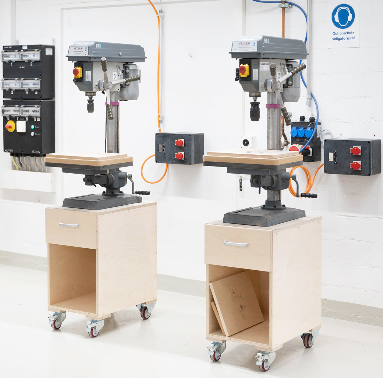
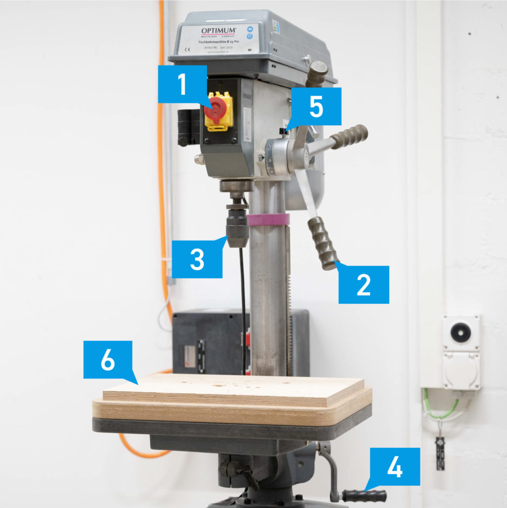
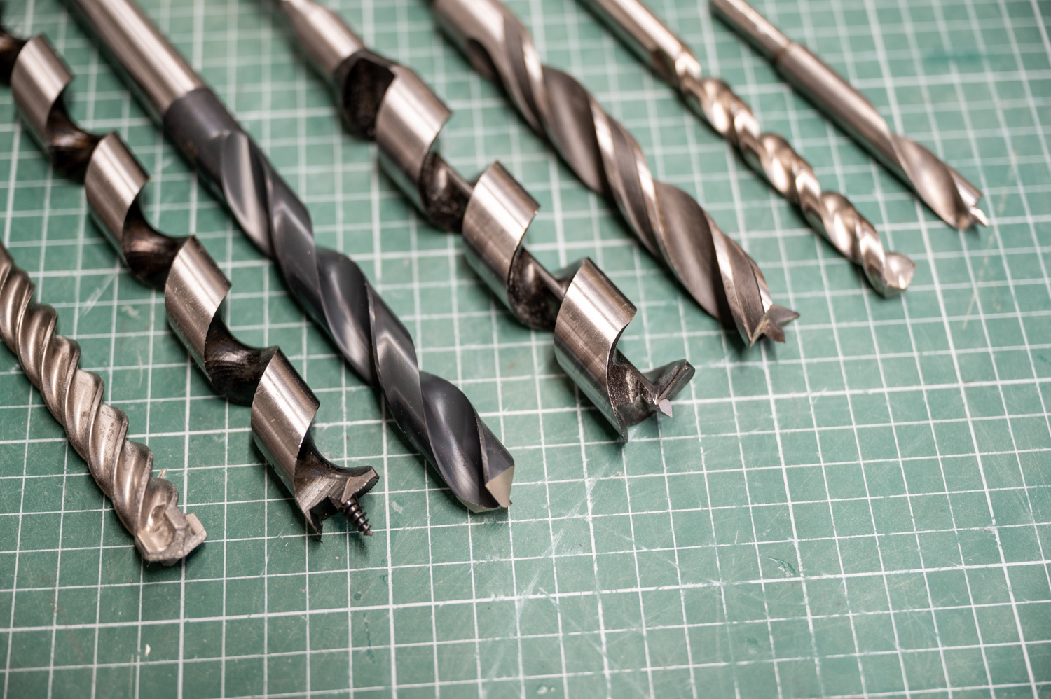
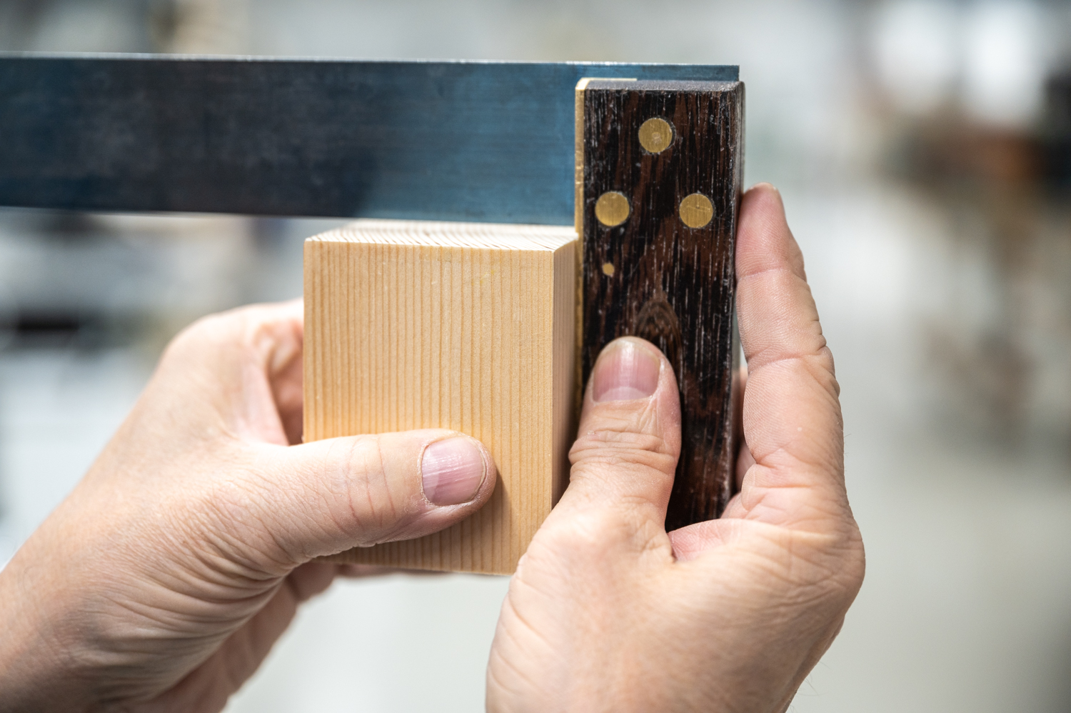
The drill press seems to be a simple tool at first glance. Considering the various types of drill bits and their particular application raises the level of complexity of this simple machine considerably. 
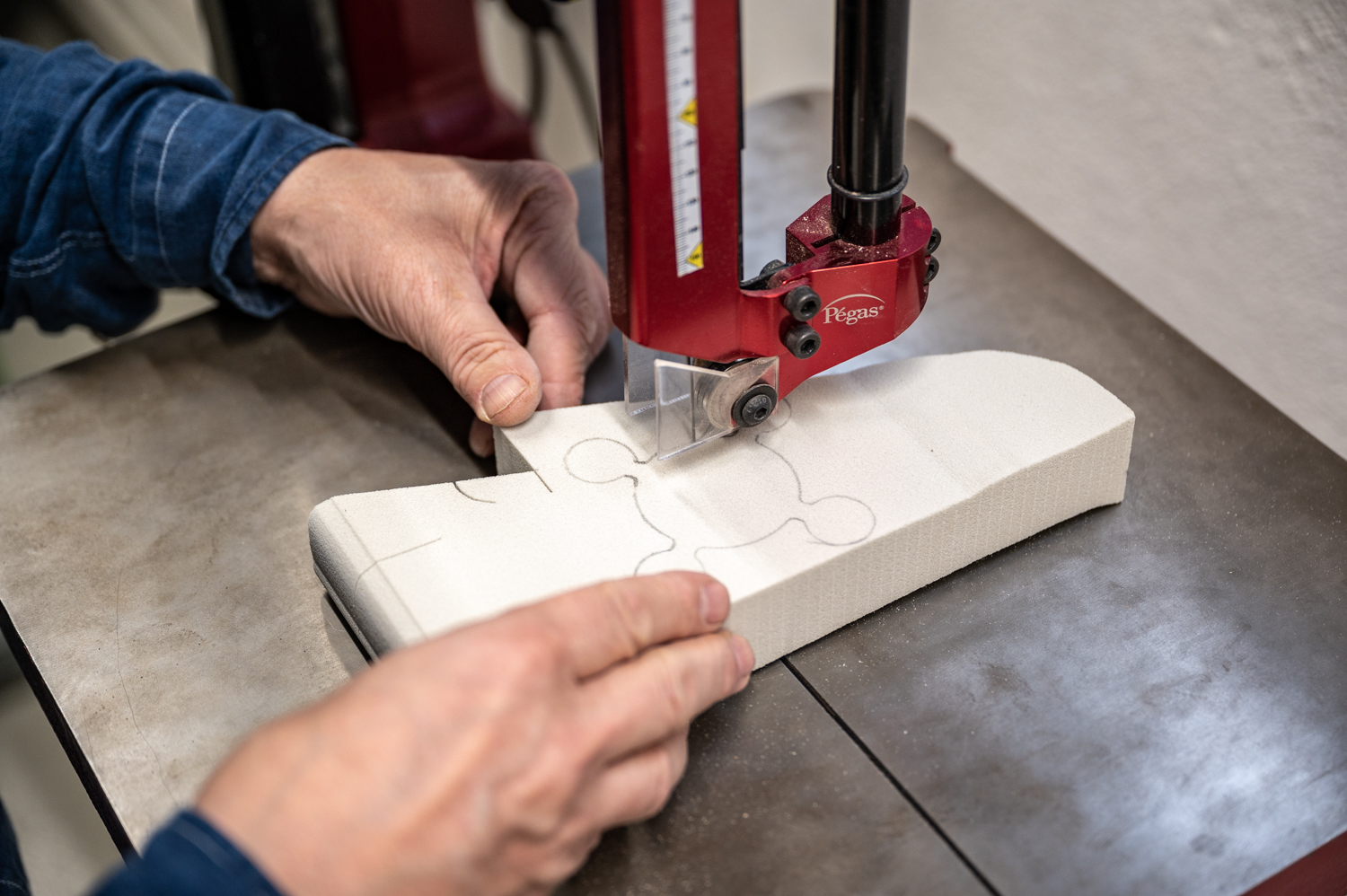
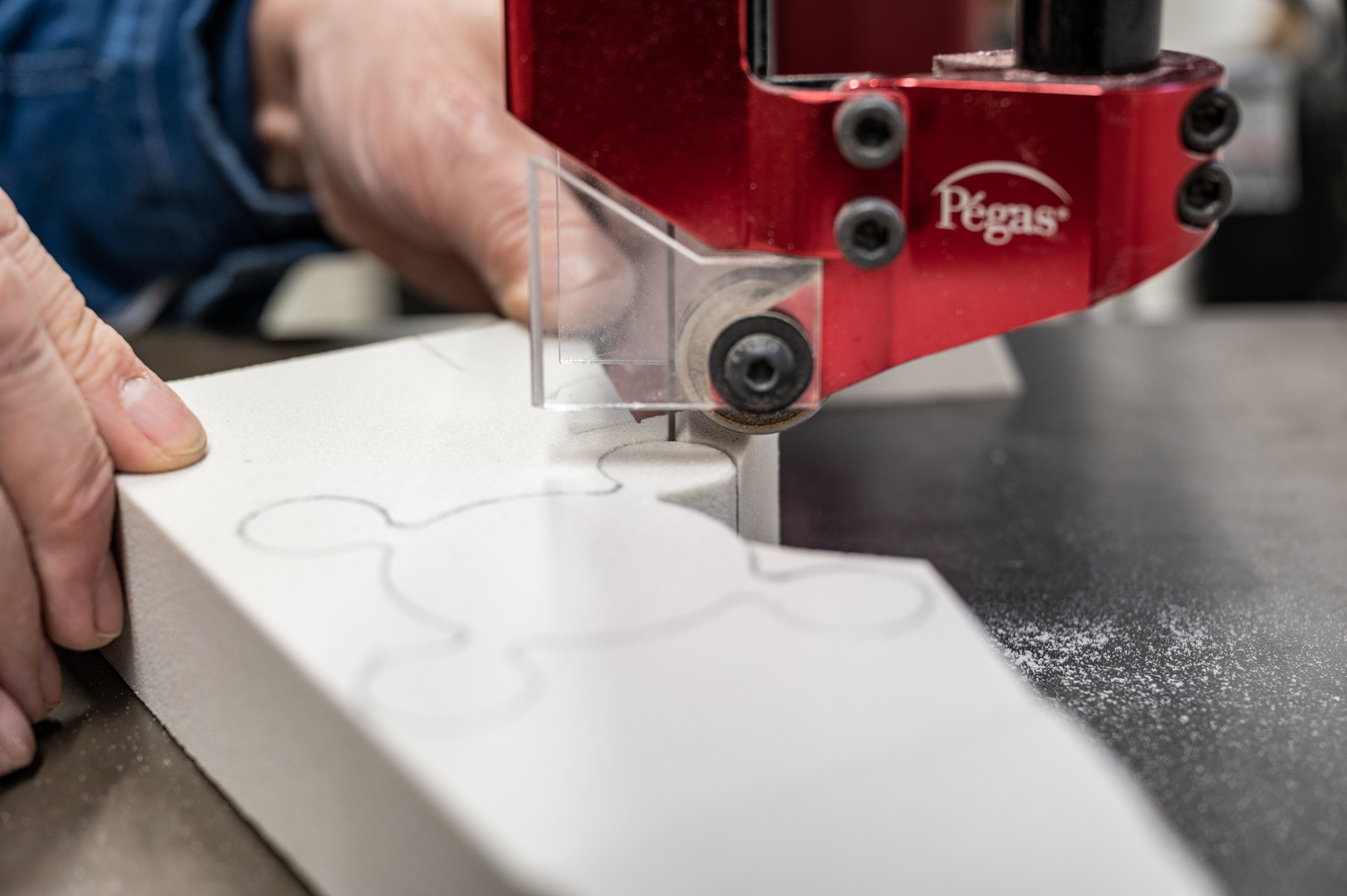
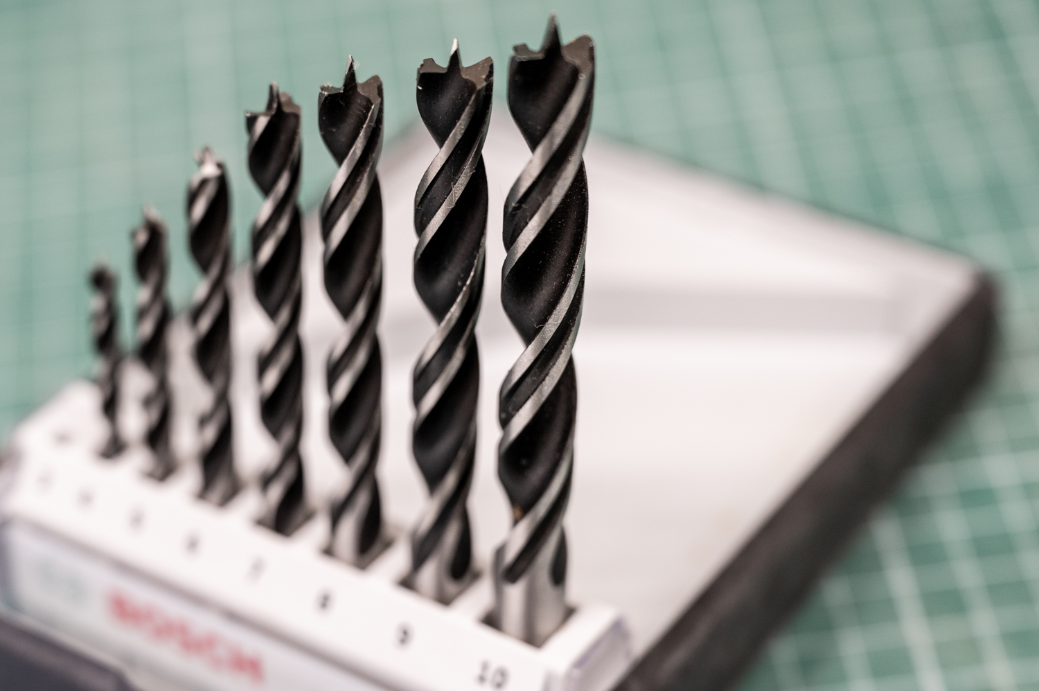
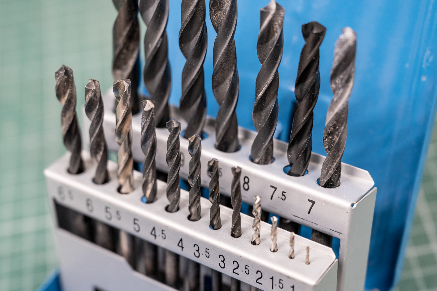
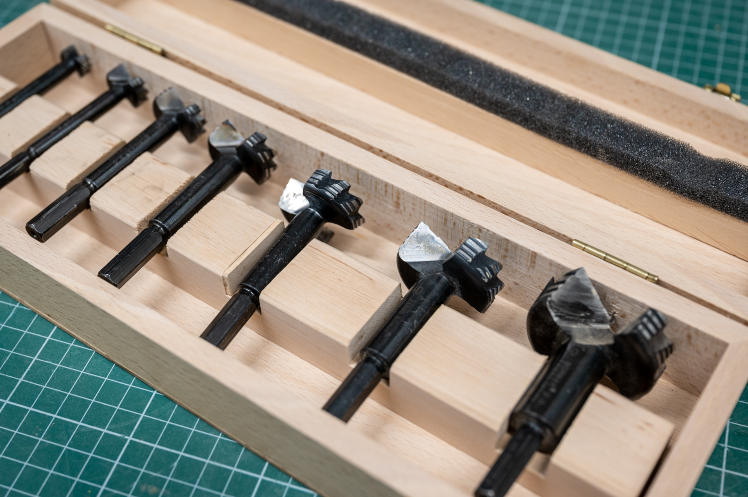
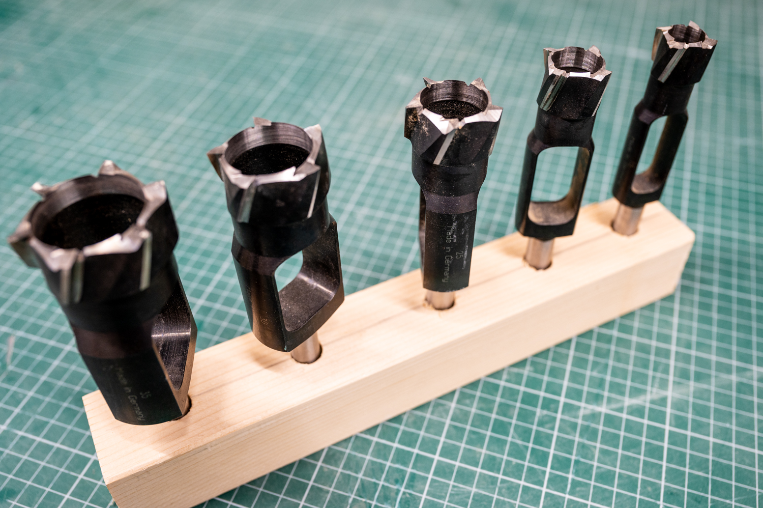
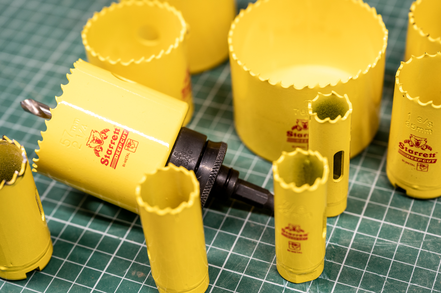
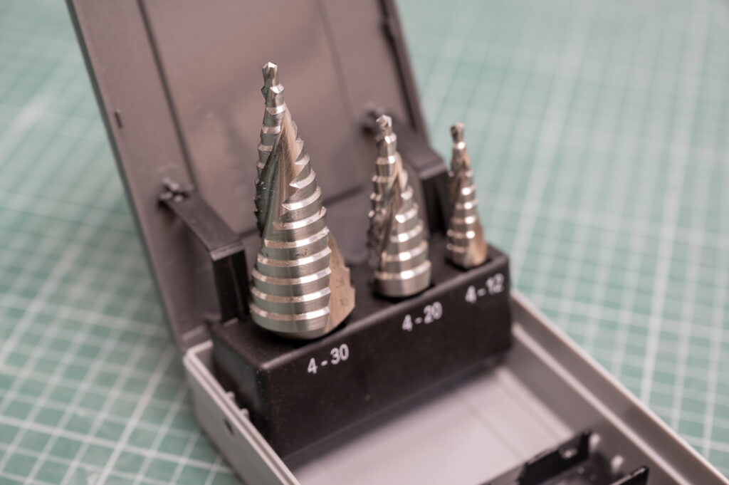
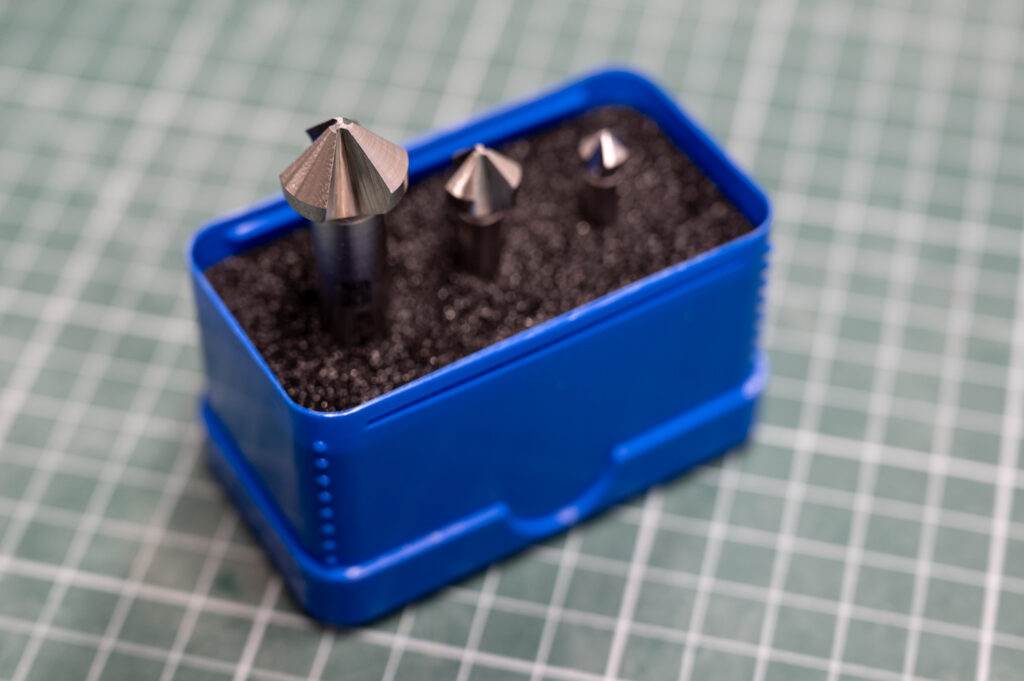
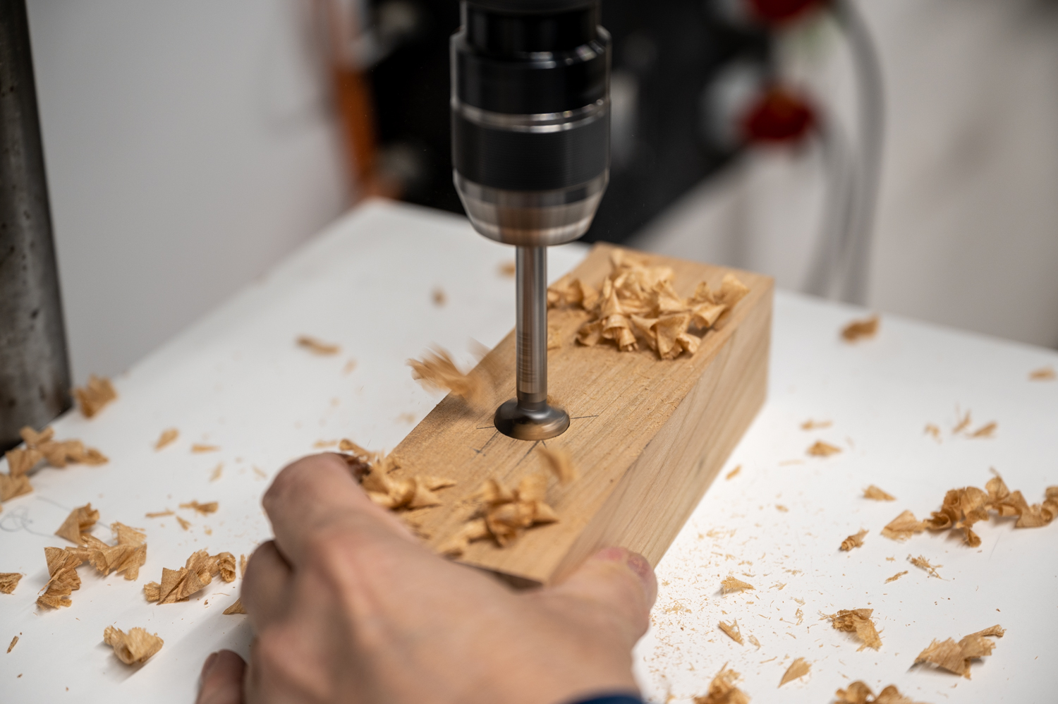
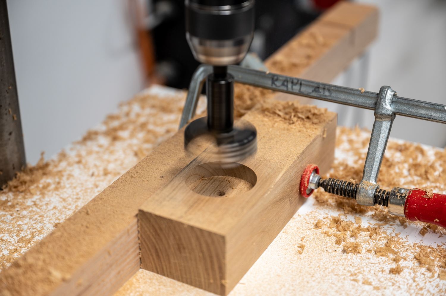
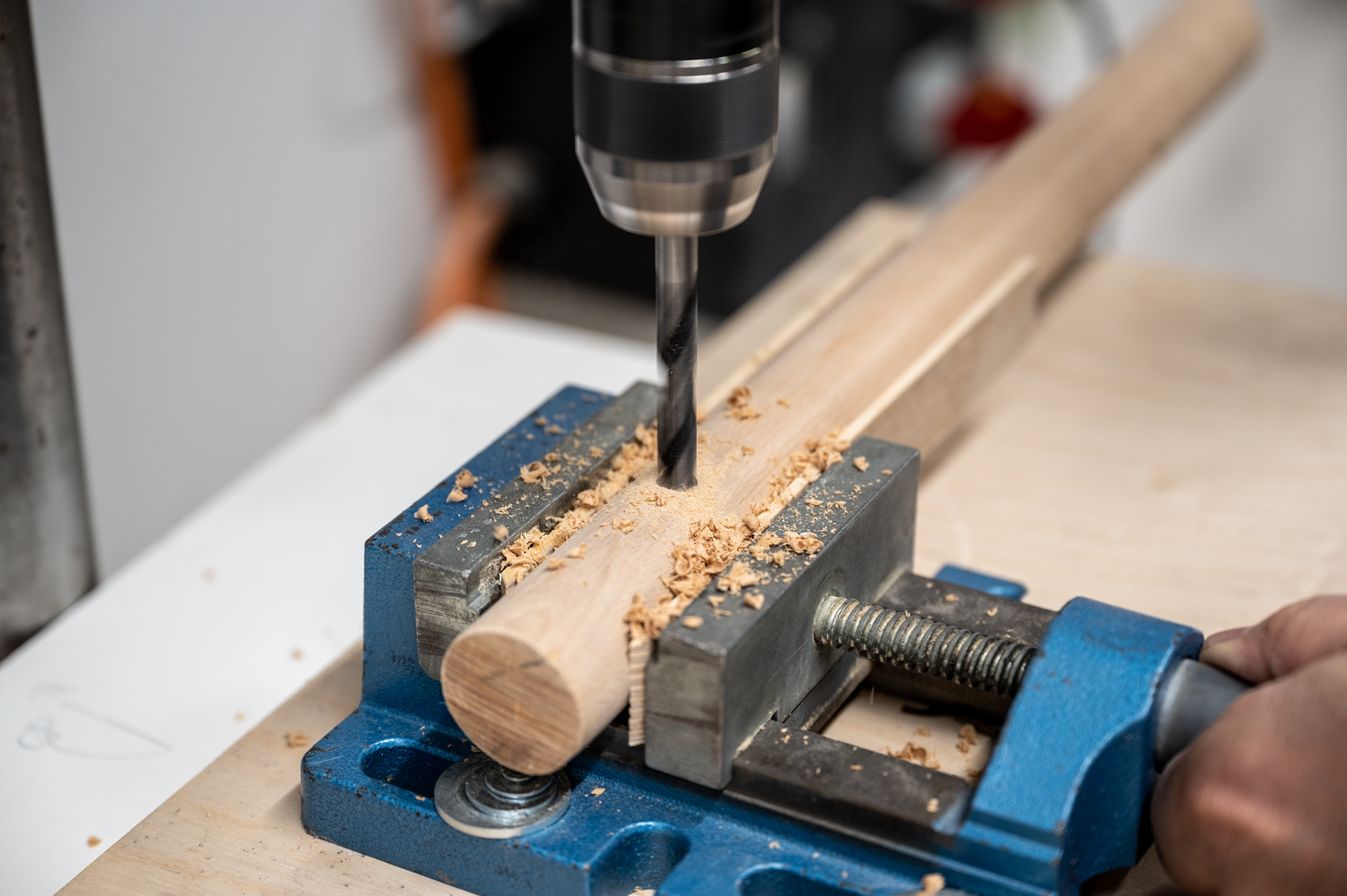
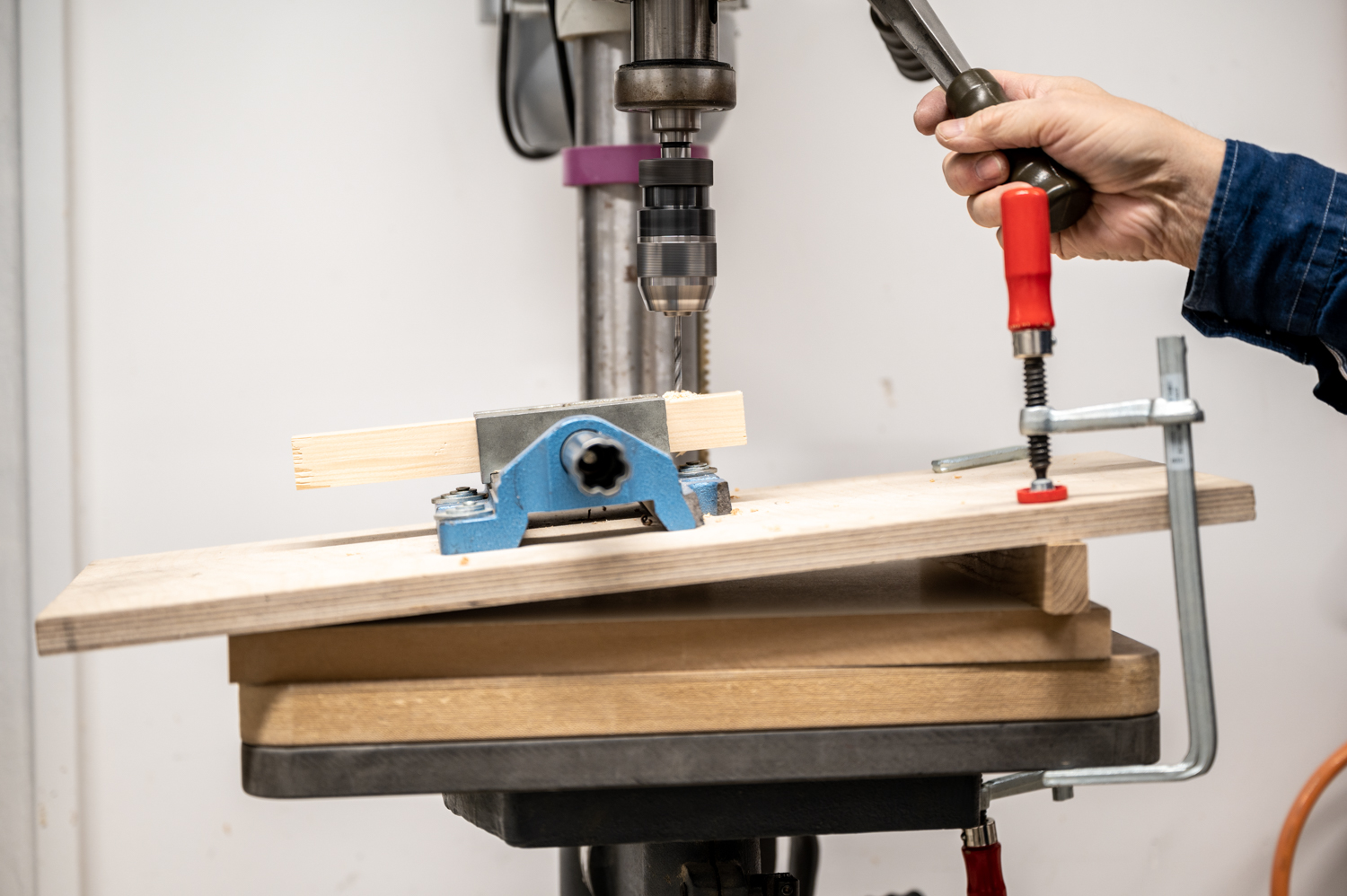
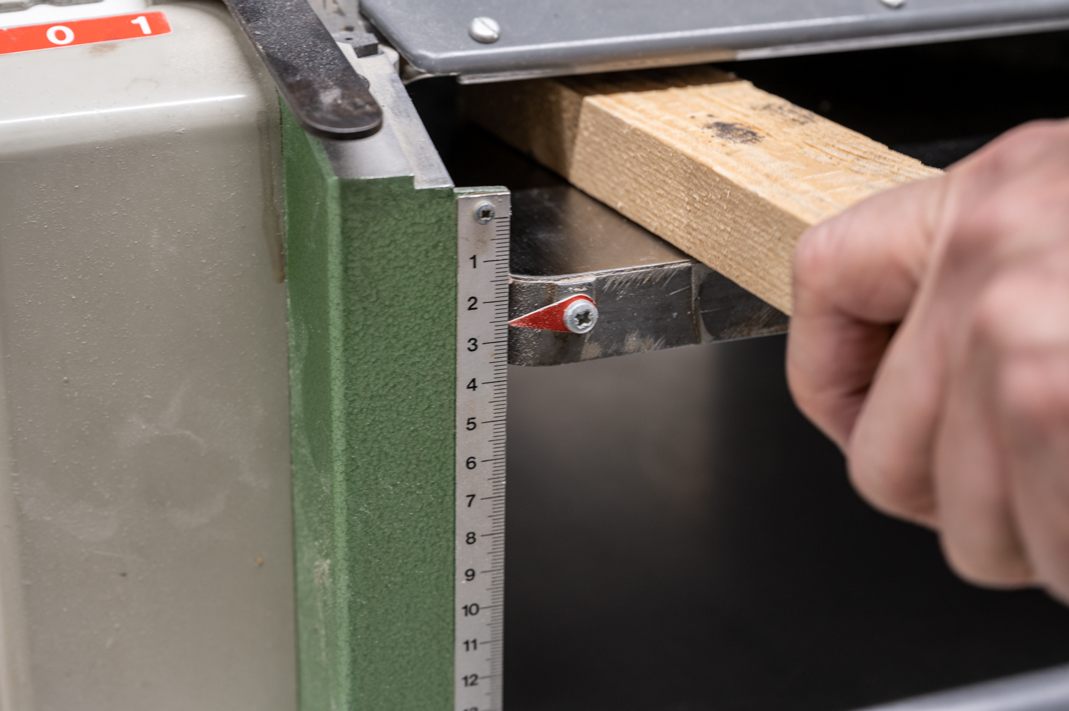
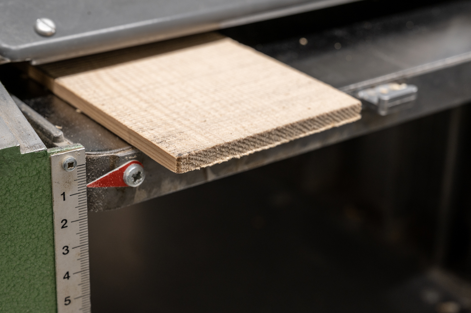
Standard operations, like drilling holes in wood with bit diameters up to 10mm, are safe if the workpiece is large enough or a work-holding solution like a vise is used to hold the workpiece securely. All larger diameter holes or different materials require specialized setups. Ask our staff for help with drilling none-wood materials and for how to use specialty drill bits (Forstner bits, hole saw, … )

Scroll Saw

Scroll Saw

Introduction

The scroll saw is a typical model builder’s or toy maker’s tool used to make intricate shapes in plywood and similar sheet material. The fine-tooth sawblades allow for tight curves, sharp turns, and immaculate control. The ability to thread the sawblade through small holes allows for internal cutouts that are otherwise only possible with a laser cutter.
The scroll saw is typically used to cut iso-curves for landscape models, detailed facade parts, and intricate scale figures.

Scroll Saw Overview

#1 Power switch
#2 Speed regulation
#3 Drop foot
#4 Lock for drop foot height adjustment
#5 Tensioner cutting blade
#6 Top blade retention wing nut
#7 Air Assistance

Machine Handling

Preparation

Adjust the drop foot (#3) to the material thickness to avoid vibration before starting the machine. The lowering foot is set correctly when it touches the workpiece lightly without exerting pressure. Use the scroll bandsaw instead of the scroll saw for material thicker than 20mm.

Set the speed (#2) to slow before starting the cut, and use both hands to guide your workpiece. Use only light pressure to avoid blade deflection. Adjust the air assist if necessary to get a clear view of the cut. 

How To

A frequently used technique demonstrated in the image above requires the saw blade to be inserted into the workpiece through a hole to create an internal cut-out.

Sawblade Replacement

To replace the blade or to insert it into a hole, loosen the tensioning lever and loosen the wing nuts at the top and the bottom of the blade holding mechanism. Note that it is sometimes necessary to remove the drop foot to get easier access to the blade!

Insert the new saw blade with the teeth facing downwards into the holding mechanism, tighten the retaining screws, and tension the blade. Pluck the blade like a guitar string; the blade is properly tensioned if you hear a high-pitched ringing sound. 

Acceptable Materials

Available Machines

  • Cutting width: 530mm
  • Table size: 580mm x 340mm

Risks

  • Cuts from pushing the workpiece by hand
  • Flying debris from shattering material

Work Safety

  • Adjust the drop foot before turning the machine on to avoid vibration
  • Adjust the cutting speed before turning the machine on
  • Do not cut material above 20mm 
  • Wear proper workshop clothes
  • The workpiece must rest on the table at all times

Summary

The scroll saw is mainly used for cutting iso-curves for landscape models and other intricate details that require tight curves. The ability to insert the blade into holes opens up the possibility for internal cut-outs. This is the only machine in the Raplab where you can replace broken saw blades by yourself.

Spindle Sander

Spindle Sander

Introduction

A spindle sander is a complementary tool to the disc sander and the belt sander. It works best for sanding concave curves on sheet material or solid wood. 
In model building, the spindle sander is used to work on prototypes and sand iso curves for landscape models.

Spindle Sander Overview

 #1 Power switch
#2 Sanding spindle
#3 Securing knob, 0_45°
#4 Table insert

Machine Handling

    How To

    Use the bandsaw to cut your workpiece roughly to shape before sanding, and do not try to remove all material with the spindle sander. This practice will save you time and effort in your model-making endeavors. Make sure to support your work on the machine table at all times.

    As part of safe working procedures, we recommend using both hands and applying only light pressure to remove material. Move the workpiece to avoid heat accumulation, and let the machine do the work for you. This gives you better control over your actions and results in a neater job. 

    Always make sure to use the correct size spindle for the work you do. Contact our staff if you see that the spindle is too large or too small and needs changing to work for the type of radii you want to achieve. 

    Acceptable Materials

    Available Machines

    • Diameter: 100mm
    • Max. height: 160mm
    • Rotation speed: 1440 – 2870 /min
    • Table size: 500mm x 500mm
    • Diameter: 6mm – 50mm
    • Max. height: 152mm – 190mm
    • Rotation speed: 1400 /min
    • Table size: 370mm x 370mm

    Risks

    • Abrasion injury from coming into contact with the sandpaper
    • Exposure to large quantities of wood dust 

    Work Safety

    • Try to sand as little as possible and use other tools to remove the bulk of the material
    • Support your workpiece on the work table at all times
    • Choose the correct spindle size for your work
    • Avoid excessive force and let the machine do the work

    Summary

    The spindle sander is ideal for sanding concave curves and shaping odd-shaped workpieces. It falls into the category of specialty machines that do an excellent job with one particular task only – but are, for that reason, tremendously helpful in the workshop. It is worth mentioning that belt sanders sometimes come with a spindle sander functionality.  Dust collection is notoriously tricky on spindle sanders due to the machine’s construction, and attention to dust accumulation must be paid during work.

    Planer

    Planer

    Introduction

    The planer is used to plane solid wood to a defined thickness and is a helpful machine for adjusting the size of laths. When using the planer, be sure only to plane the faces that are side- or flat-grain and avoid end-grain altogether. Use the disc sander to remove small amounts of material from the end grain.
    Model builders use the planer to bring the stock to a specific dimension before cutting it to length on the bandsaw or with other machines and techniques. This order of operation is essential because the planer can only handle pieces longer than 250mm due to its construction with the infeed-, cutter head, and outfeed roll. 

    Machine Overview

    Planer Overview

    #1 Power switch
    #2 Feed rate shift handle
    #3 In/out feed table
    #4 Table raising/lowring handwheel
    #5 Debth of cut scale

    Machine Handling

    Preparation

    The planer is strictly made for processing clean, dry, solid timber without any fasteners or nails inside. Other materials can damage the machine or result in injury and must not be used on this machine. The workpieces to be planed have to be flat on at least one side and can not be shorter than 250mm.

    Only the surfaces of long grain (#1) can be planed with a planer. Never try to plane the end-grain part of the wood (#2). You risk damaging the machine and seriously injuring yourself.

    As a first step, measure the thickness of your stock precisely to dial in the machine table correctly. To obtain a good result, set the machine between 0.5 and a maximum of 1mm less than the thickness of your workpiece by adjusting the table height with the handwheel (#4). 

    Turn the machine on and feed your workpiece into the machine with the side to be planed facing upwards. When the feed roller pulls the piece in, let it go, and do not guide or push the workpiece anymore. If your material gets stuck in the planer, turn the machine off, lower the table with the handwheel and remove the material carefully. Never reach inside the planer; there is a severe risk of injury if you do so!

    How To

    The Inca automatic planer available at Raplab works best for smaller jobs. Thicknesses of approx. 5-100mm can be processed. The wider your workpiece is, the less material you can remove per pass. An indication of removing too much material is that the motor loses speed, characterized by an audible drop in machine noise.

    The picture shows two pine laths. One is in a raw state coming directly from a sawmill, and the other is fresh from the planer. Guess which is which?

    Acceptable Materials

    Available Machines

    • Max. width: 260mm
    • Max. depth: 160mm

    Risks

    • Injuries from pinching or bruising your hands
    • Injuries from kick-back
    • Cuts from getting in contact with the cutter head 

    Work Safety

    • This machine can only be used under the supervision of a staff member
    • Use only clean solid timber, free of metal pieces (nails, screws, …)
    • The workpiece must be flat on at least one side
    • Never reach inside the planer to remove stock
    • Respect the minimal dimensions that the machine can handle
    • Pay attention to the order of operation; planing before sawing 
    • Do not remove more than 1mm at a time
    • Never put your hand into the machine
    • If your workpiece is stuck in the machine, turn off the machine and lower the table before getting it out.

    Summary

    The planer or thicknesser creates parallel and smooth surfaces on a piece of wood. It is ideal for adjusting the dimensions of a workpiece before cutting it to size and using it in a model of a timber frame building, for spatial grids, or trusses. 
    The machines at the Raplab are for precise work on elements for model building and require clean and well-prepared stock to begin with. Rough and uneven timber can not be used, and material of unknown origin should be shown to the staff before use. Safe operation of the machine is unproblematic as long as you comply with the essential work safety rules.

    Belt Sander

    Belt Sander

    Introduction

    The belt sander provides a fast and efficient way to clean up the edges of boards and shape objects with a convex curvature that can not be sanded on the disc sander due to size limitations.
    In model building, the belt sander is primarily used to clean up the edges of landscape models and sand parts for facades or similar larger-scale elements to final dimensions. The tilting function of the machine allows for the precise sanding of miters to join components seamlessly. Small parts are not to be used on this machine due to the force sanding exerts on the workpiece, making work holding difficult.

    Belt Sander Overview

    #1 Power switch
    #2 Sanding belt
    #3 Belt direction
    #4 Spindle
    #5 Miter Gauge

    Machine Handling

    How To

    To clean up the edge of a workpiece hold the part with both hands and work from right to left, against the belt direction (3) to counteract the force from sanding. Do not advance your workpiece from the left side to avoid injuries. 

    Do not sand the short edge of a workpiece on the belt sander. The right, and far safer option, for this task is the disc sander!

    Always support your workpiece on the machine table, and use only light pressure to avoid heat accumulation. Remember: the machine should do the work for you! The belt sander is ideal for removing the last .5mm material; anything more than that should be removed with the bandsaw

    The miter gauge can be used as a backstop to support the workpiece while sanding. Using the backstop helps with accuracy and is an effective way to avoid injury because it prevents the workpiece from getting thrown off the table. 

    For sanding beveled panel edges, tilt the belt sander to the desired angle and adjust the machine table to avoid more than 2mm gaps between the belt and the table.

    Acceptable Materials

    Available Machines

    • Sanding height: 125mm
    • Sanding area : 125mm x 550mm


    Risks

    • Abrasion injury from coming into contact with the sandpaper

    Work Safety

    • Use the miter gauge as a backstop 
    • The workpiece must rest on the machine table at all times
    • Make sure that the workpiece is appropriately oriented
    • Small parts should be sanded by hand or with the disc sander
    • Check the distance between the work table and the sanding belt before turning on the machine and adjust it if necessary

    Summary

    The belt sander is used for sanding the edges of boards and models. As with any sanding machine, we use it to remove the last millimeter, clean up cuts made with other machines, and not remove substantial amounts of material. Utilizing the miter gauge as a backstop adds an additional safety layer and prevents workpieces from flying off the table. 

    Band Saw

    Bandsaw

    Safety Guide Lines

    • Use push sticks or blocks – keep your hands off the blade! 
    • Adjust the guide post to the workpiece thickness +2cm
    • Keep the worpiece flat on the worktable

    Introduction

    Bandsaws are typically used to cross-cut stock to a specific length, to rip material to width, or for joinery applications. The Bandsaw can be regarded as an advancement to manual sawing and helps speed up many operations that can also be done with a good handsaw
    In our context, model, and prototype building, the bandsaw primarily prepares wood for final sanding on the disk sander. To execute our cuts, we either measure the distance from the sawblade to the fence while the saw is turned off, lay out our parts with pencil and cut to the line or print a template and mount it with spray adhesive to have a guide for cutting and sanding.

    Machine Overview

    #1 On/Off switch
    #2 Saw blade guide assembly
    #3 Rip fence
    #4 Bin for offcuts
    #5 Knob/wheel to adjust guide (#2) position
    #6 Knob to lock height adjustment (#5)
    #7 Guide post

    Machine Handling

    Sawblades

    With a band saw, straight and curved cuts are possible, depending on the width of the blade. Wide blades (12-100+mm) are suitable for straight cuts and resawing. The blade shown here is a general-purpose blade used for rip- and cross-cutting of wood and wood products.

    Narrow blades (1-8mm) facilitate curved cuts and allow for intricate work. The blade shown here is from our scroll bandsaw and is typically used for extremely small radii and cutting softer materials like styrofoam. 

    Blade Guard Adjustment

    Before turning on the band saw, set the machine in the correct position. The guide unit (#2) must be placed about 10mm above the workpiece and all workpieces must lay flat on the machine table.

    In this image, the guide unit (#2) is not set correctly, and too much blade is exposed, leading to an inaccurate cut result and a potentially dangerous situation where the blade guard is ineffective in preventing injuries.

    Rip Fence Settings

    Use the rip fence if you need a straight cut with a precise width (#3). Please note that materials thicker than 80mm cannot be processed on our band saws. 

    If the machine has two rip fences, the taller one is exclusively for resawing stock. Smaller stock should be cut with the lower rip fence to allow for the correct positioning of the blade guard. 

    Push Sticks And Push Blocks

    Use the official push sticks when you cut material close to the blade to protect your hands from injury. Your hands should always be further away than 10cm from the blade!

    Other helpers and push blocks can be used if the push stick is not practical. They should be made of wood and protect the pushing hand adequately.

    Curved Cuts

    Cutting curves on a bandsaw with a broader blade is possible if you create incisions along the curve first, as shown in the image above.

    This technique reduces the amount of curvature between the individual segments significantly so that the blade is able to follow the line accurately.


    Miter Gauge

    Use the miter gauge in combination with the rip fence for repetitive cuts. Combining the two fences guarantees accurate and repeatable results and puts your hands out harm’s way.

    The miter gauge can be set to any angle between +/-45 degrees and helps to produce precise mitered cuts. 

    Additional Bandsaw Jigs

    Jigs become necessary for cutting workpieces that do not have flat support or cannot be guided easily on the machine table. These jigs can vary from simple dowel-cutting helpers to complex and elaborate setups for “free-form” work. 

    The Raplab has prefabricated jigs that allow safe and precise cutting of the most common angles to produce profiles useful in architectural model making.

    1 Cutting jig 45° (also available, 22.5° / 26.6°)
    2 Clamp to attach the aid to the rip fence
    3 Workpiece

    Cleaning

    After the cut, switch off the machine and wait until the sawblade stands still before retracting the workpiece or removing any off-cuts.  Always clean the machine and its surroundings after use to prevent accidents and to provide a productive environment for the next person.

    Acceptable Materials

    Available Machines

    • Cutting width: 565mm
    • Table size: 610mm x 870mm
    • Cutting width: 365mm
    • Table size: 515mm x 400mm
    • Cutting width: 575mm
    • Table size: 560mm x 850mm

    Risks

    • Cuts from pushing the workpiece by hand
    • Cuts from not correctly adjusting the blade guard
    • Injury from breaking the saw blade

      Work Safety

    • Adjust the blade guard to the appropriate height (10mm above the material)
    • The workpiece must rest on the machine table at all times
    • Use push sticks, push blocks, and the miter gauge to protect your hands
    • Keep your hands at a minimum safe distance from the sawblade at all times (approx. the distance of your fist)
    •  As a general guide, do not cut materials thicker than 80mm
    • Never work from behind the bandsaw, pulling the workpiece
    • Switch to the appropriate saw depending on the size of your workpiece
    • Turn the machine off and wait until the sawblade stops moving before pulling your work back or before removing any offcuts
    • Use only acceptable materials
    • Please adhere to our general work safety guidelines (link)

    Summary

    The bandsaw is one of the safest machines in the wood workshop if a couple of basic rules are considered before turning on the machine. The machine is mainly used to prepare stock for sanding or planing. The proper use and adjustment of the blade guard, the push stick, and the push block dramatically decreases the risk of injury and helps with accurate cuts. The workpiece must rest securely on the work table at all times, and custom setups must be developed for round stock or workpieces with no flat side.

    Disc Sander

    Disc Sander

    Safety Guide Lines

    • For small workpieces use sanding jigs – keep your hands off the blade! 
    • Use only the left half of the sanding paper
    • Keep the worpiece flat on the worktable

    Introduction

    The disc sander is used as a quick way to clean up saw marks left behind from the band saw and helps precisely remove material from a workpiece.
    In model building, the disk sander is generally used for smaller parts and cannot handle long edges that extend over the left half of the disk or tall objects. We typically use it for volumetric objects like buildings on a scale from 1:500 to 1:100. For operations that the disk sander can not handle, we usually switch to the belt sander or sanding by hand.  

    Disc Sander Overview

    #1 Power switch
    #2 Working area
    #3 Miter gauge
    #4 Machine table retainer (90°)
    #5 Retaining screw (both sides of the machine) for changing machine table angle
    #6 Direction of rotation

    Machine Handling

    Preparation

    Make sure that the machine is correctly set up by checking the angle of the worktable with a reliably try square before turning on the device to ensure that your parts turn out the way you want them.

    To adjust the table, you must unlock it on both sides and slide it to the correct position. If you need to set up a precise angle for sanding, you can use the angle measurements at the pivoting slide below the table.

    Notice the small end stop that can be turned on the right side of the table that helps to bring the work table back to 90°. Lock the table as soon as the table is in the desired position before turning on the machine.

    How To

    The disk sander is not made to size down your workpiece. Prepare your workpiece by cutting close to the required shape with the band saw to minimize sanding.

    Use the miter gauge to sand reliably and repeatedly to accurate angles. 

    Work Holding And Checking

    Using a sanding jig for small parts is advisable to avoid injuries. Some essential jigs are provided to you in the drawer below the disk sander. Please get in touch with our staff if you need a more elaborate setup for something you want to make on the disk sander. We typically attach the workpiece to the jig with double-sided tape; this ensures that small parts are held securely.

    Even small parts can be sanded to precise dimensions and complex shapes without the risk of injury with the help of a sanding jig that places your fingers away from any potential danger zones.

    The machine table can be adjusted for custom compound angles by tilting the table downwards. Most common operations can be achieved by adequately orienting the workpiece on a 90° table. If this is impossible, only tilt the table downwards to avoid a potentially dangerous setup! 

    Check the angle of your workpiece from time to time to ensure that everything is square and parallel. The speeds on the outside of the disk are far greater than towards the center; this leads to more material being removed on the outer side. You have to compensate for this by turning the workpiece regularly or using a sanding aid with the miter gauge. 

    Accepteble Materials

    Available Machines

    • Diameter: 400mm 
    • Sanding Area: max. 190mm on the left side of the disc
    • Grit: 60
    • Diameter: 300mm 
    • Sanding Area: max. 140mm on the left side of the disc
    • Grit: 60

    Risks

    • Abrasion injury from coming into contact with the sandpaper

    Work Safety

    • Minimize sanding by preparing your workpiece properly 
    • Use only light pressure to avoid heat accumulation and let the machine do the work
    • Move your workpiece while sanding to prevent heat accumulation
    • Always support your work on the machine table
    • Sand only on the left half of the sanding disc
    • Use a sanding jig for small parts to avoid injury by coming into contact with the sandpaper
    • Critically check if sanding by hand is more appropriate

    Summary

    Remember that the disc sander removes more material on the outer side

    Use sanding jigs to guarantee parallelism and to get more accurate results