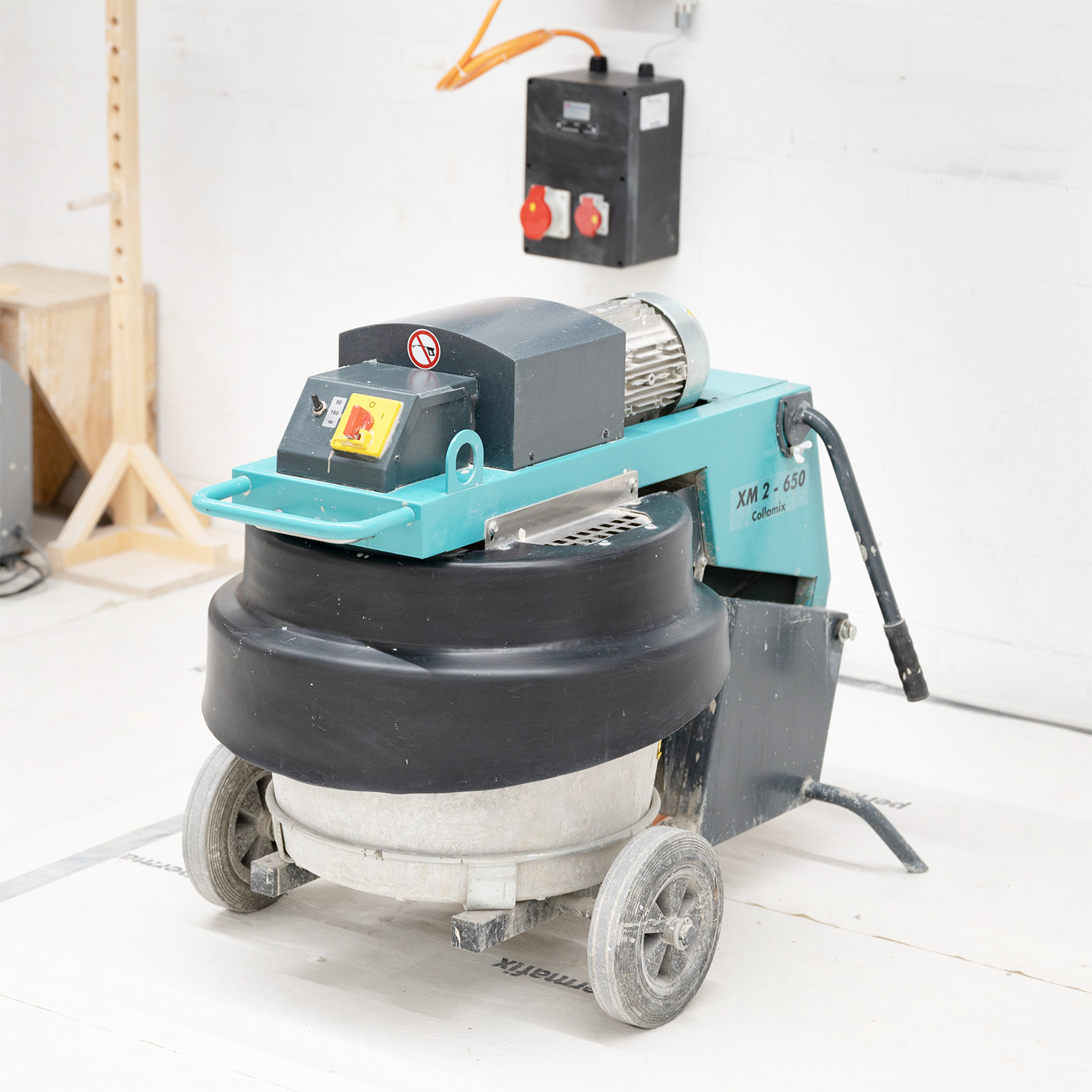
Concrete Mixer
General Information
1 machine available
For Concrete and Cement only!
In order to use this machine you must have succesfully completed the following courses:
- general safety introduction course
- introduction to the plaster workshop
- Tie long hair back
- Wear proper workshop clothes
- Wear a dust mask
- Wear safety glasses
Please check our workshop rules for more detailed safety instructions.
- Concrete
- Cement
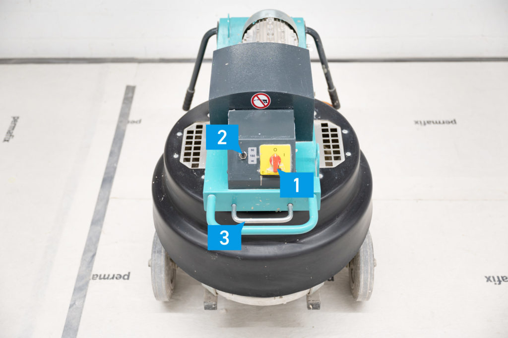
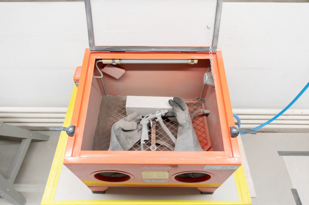
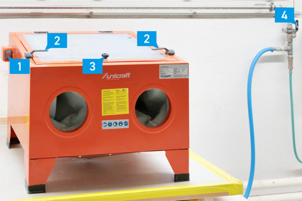
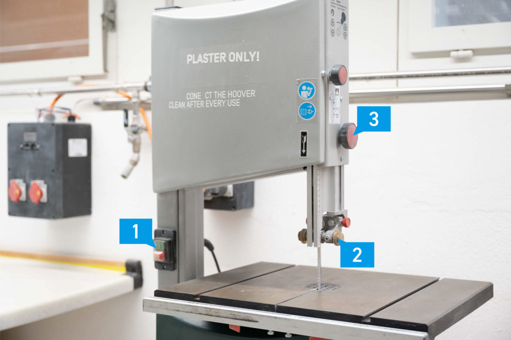
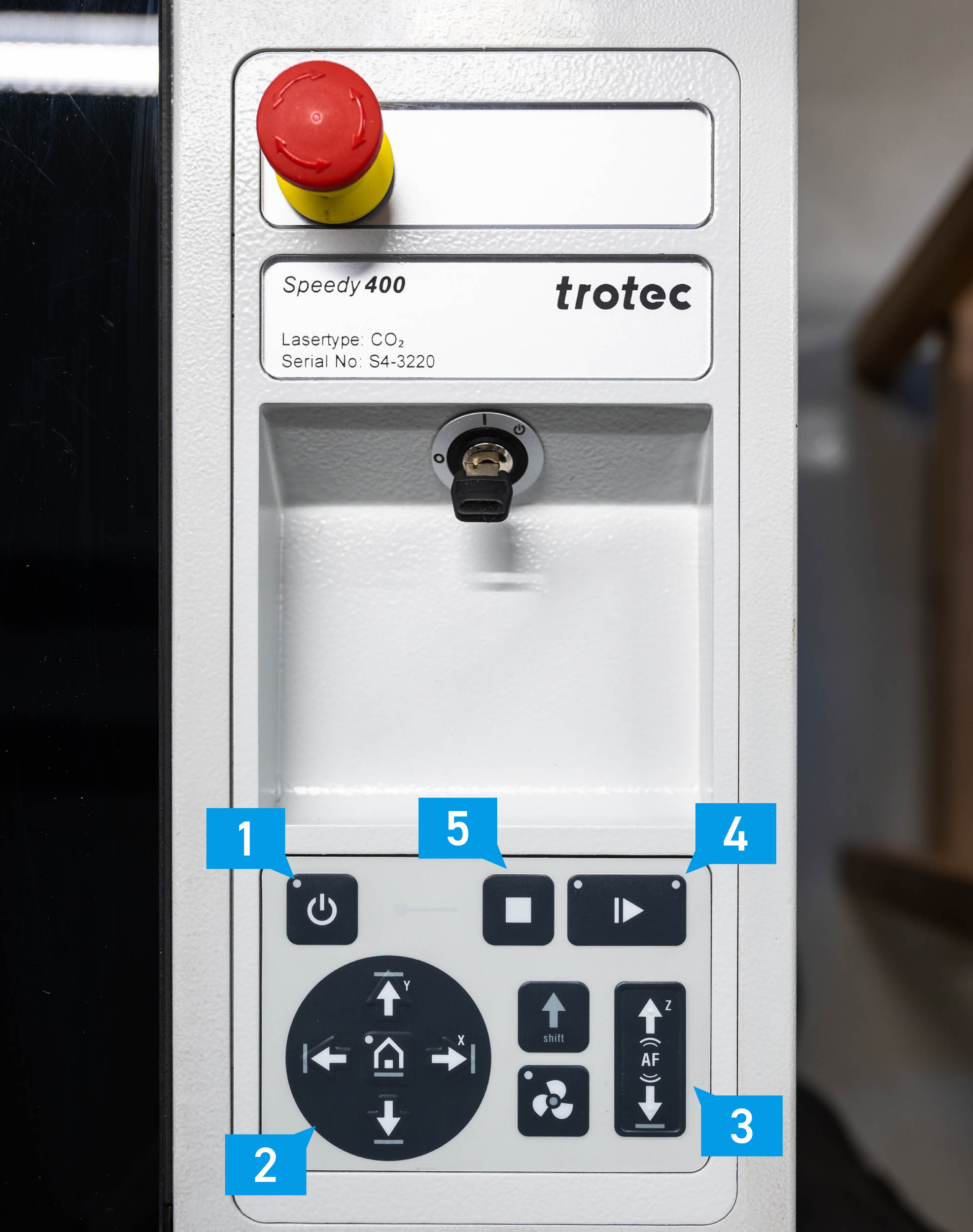
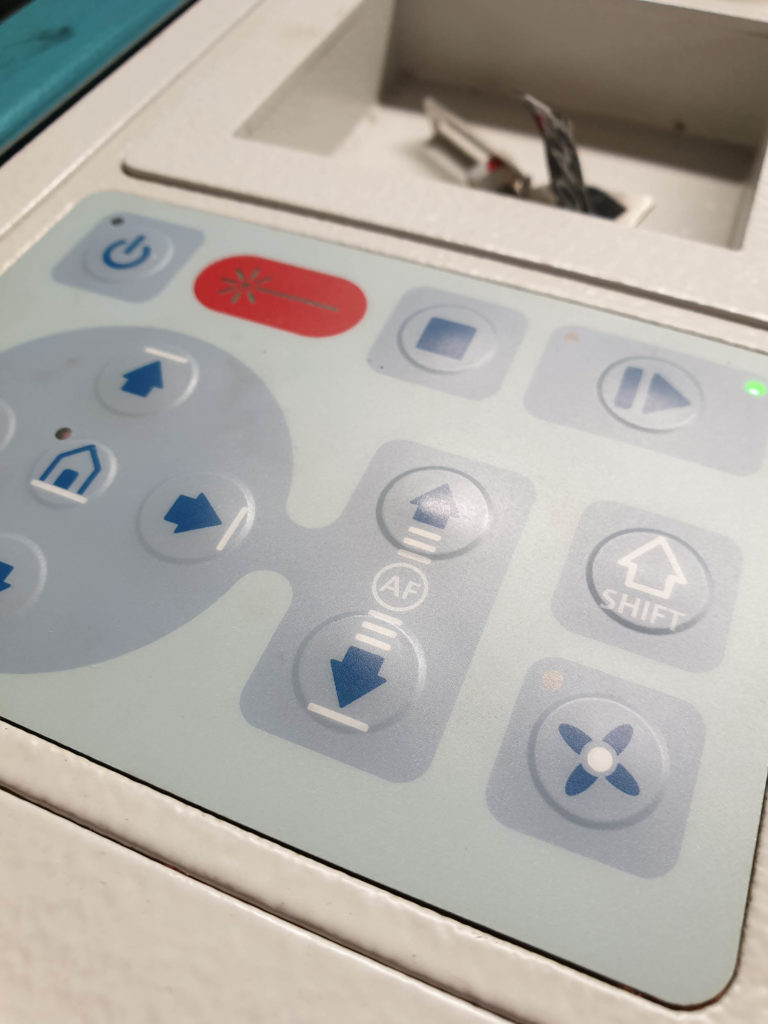
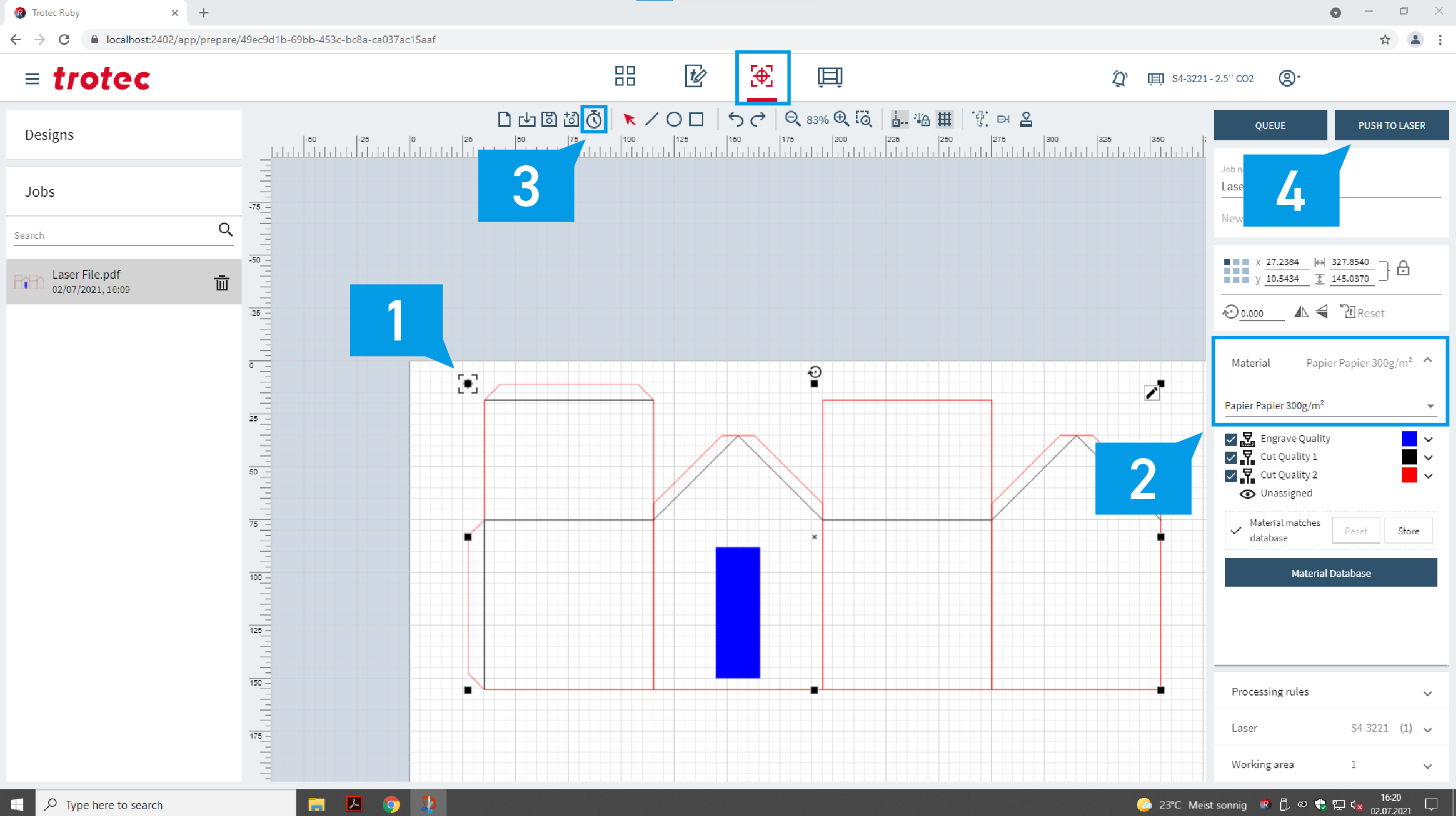
Concrete Mixer overview
- Power switch
- Timer
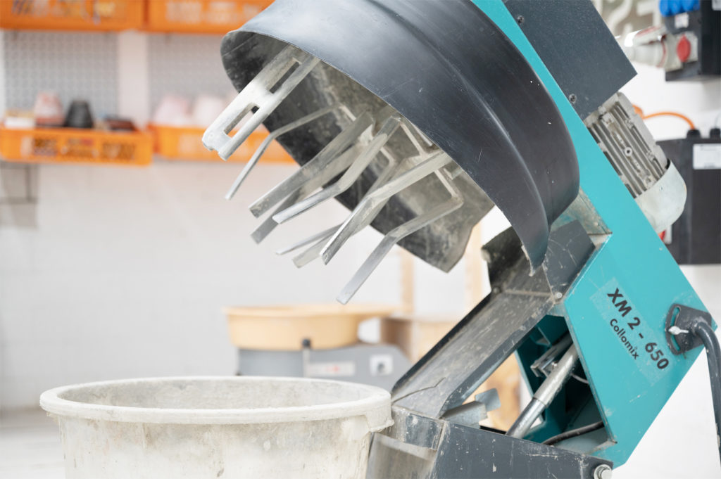
- Opening Handle
- Select mixing time (2) (90 or 180 seconds, at ∞ you have to switch off manually)
- Open the lid (3) and fill in material (less than 20 kg)
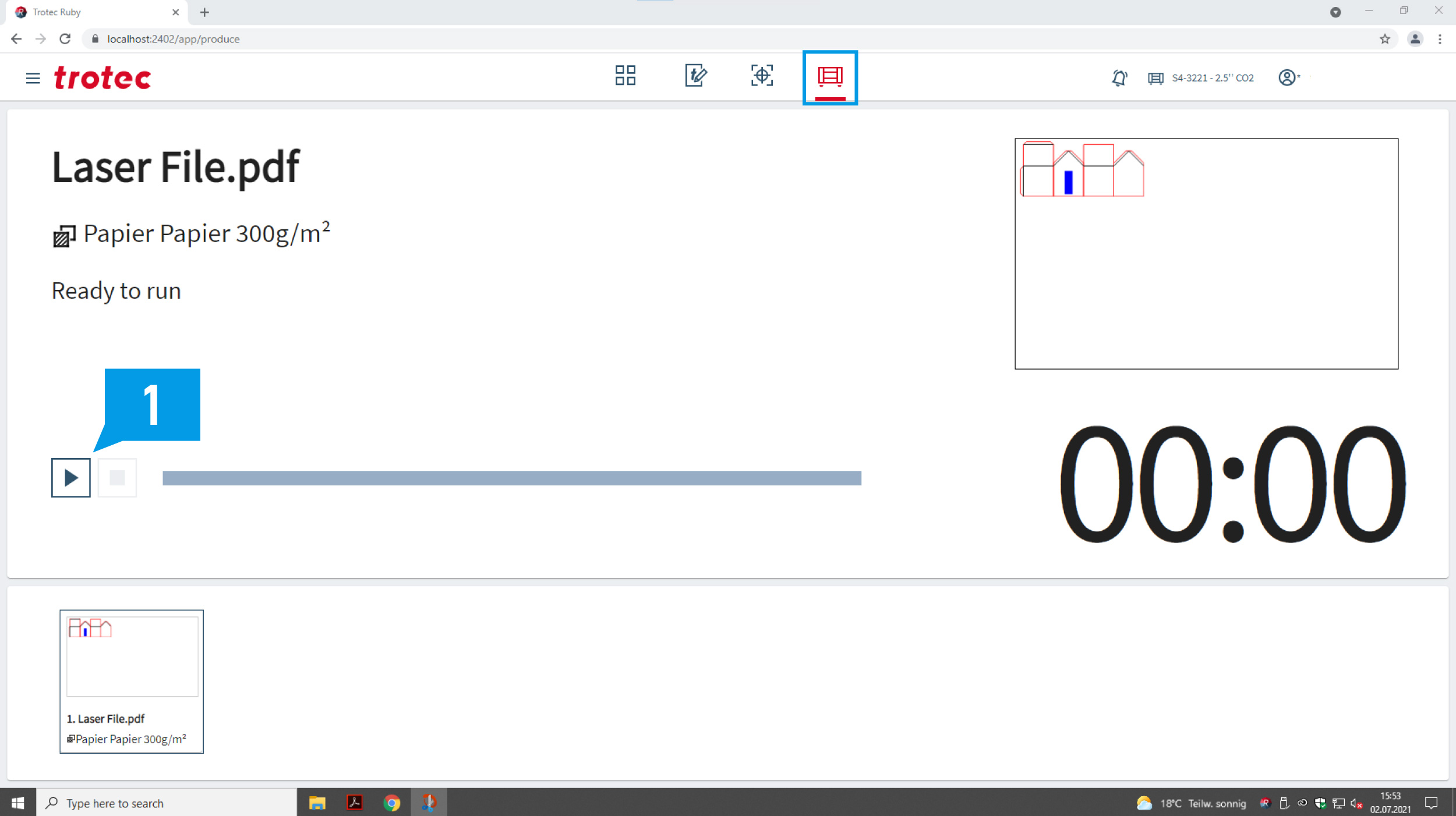
- Switch the machine on (1) during the lid is open
- Close the lid (agitation starts automatically)
- If you choose ∞ switch of the machine manually (1)
- Open the lid and remove the mixed material
- Clean the machine profoundly (bucket, stirrer and machine)
Things of importance
- Cement dusk is unhealthy; it there is a lot of dust, everyone in the room should wear a mask.
- Clean the machine immediately after use. First cleaning step is to fill water in the bucket and switch the machine on.


