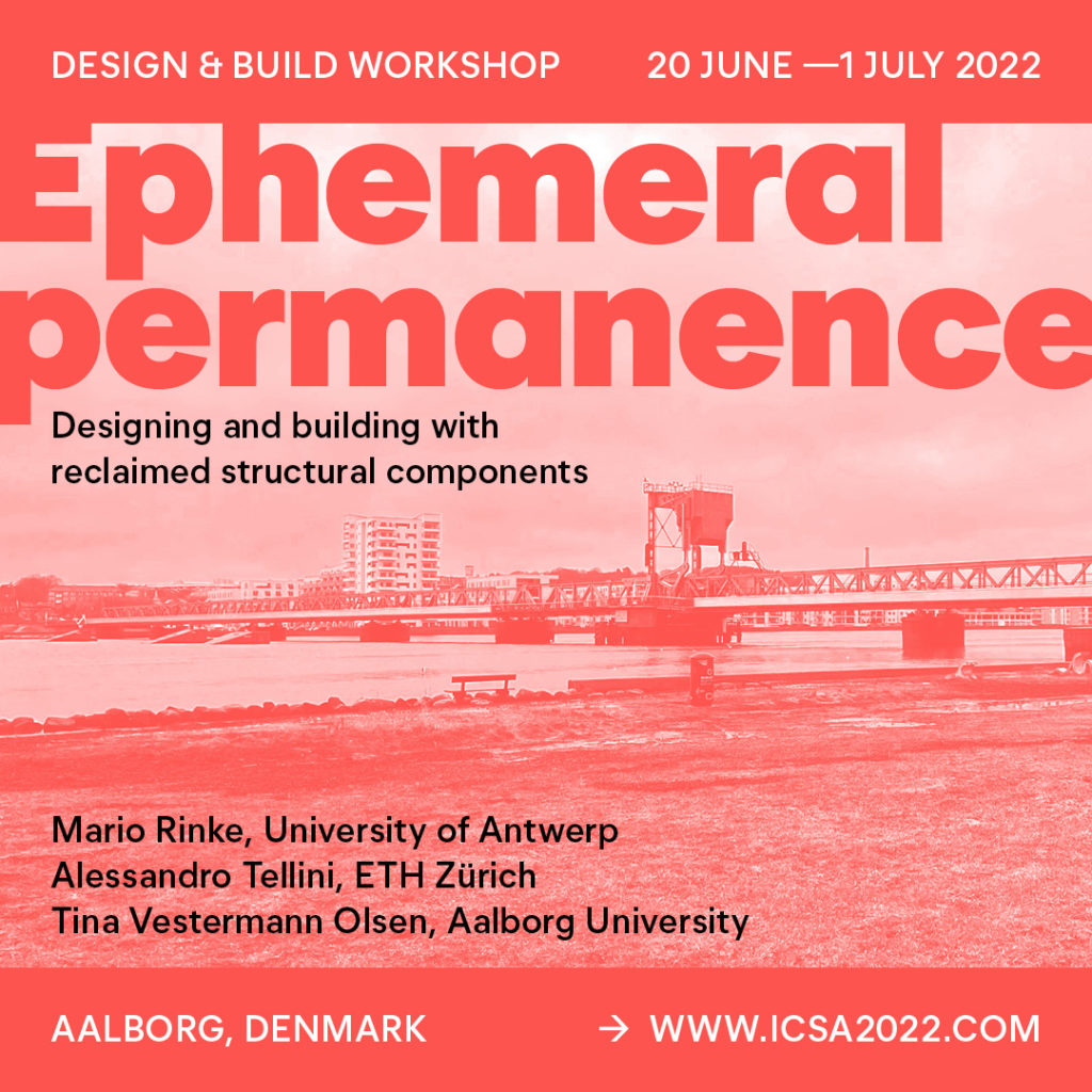
EPHEMERAL PERMANENCE 1:1
Workshop Dates: 20 June – 1 July 2022, Aalborg Denmark
CONTEXT AND GOALS
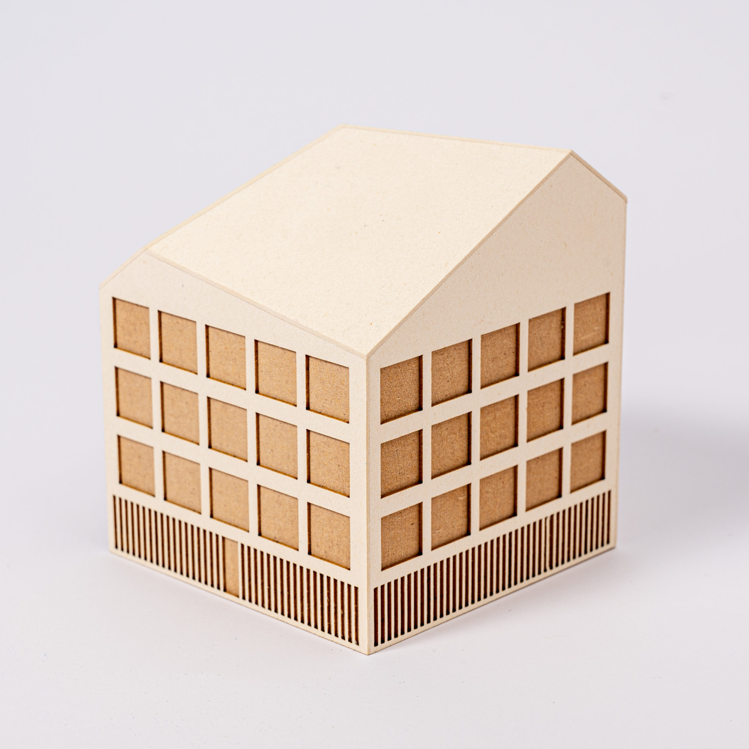
The most sustainable construction materials are those we already have. Reusing what already exists is at the heart of circular construction and a fundamental element of more sustainable architecture. If a building cannot be used anymore and faces demolition, we must at least reclaim its components. On the technical side, the major components should be recognized and reintroduced into the market. On the design side, this new broader notion of materiality pushes toward an availability-based design that also shapes the way how we decide on forms, connections, component arrangements, and spaces. This quest for circular thinking also applies to the spaces we re-create in the process, they should likewise be understood as ephemeral resources that we need to cultivate towards a viable permanent development of the urban environment. With this ambitious design and build workshop, taking place in an actual site of ongoing urban development in Aalborg, we explore this dual structural and architectural challenge, raising the questions:
How (different) would structures look like if based on reclaimed components?
Could they also directly embrace the further reuse of their components?
What new sorts of architectural spaces can be re-created here and with what urban perspectives?
Registration:
https://www.icsa2022.create.aau.dk/international-1-1-workshop/

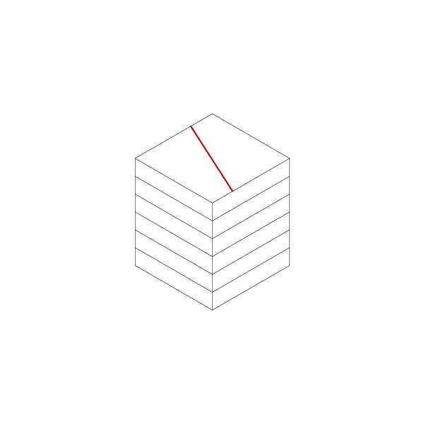
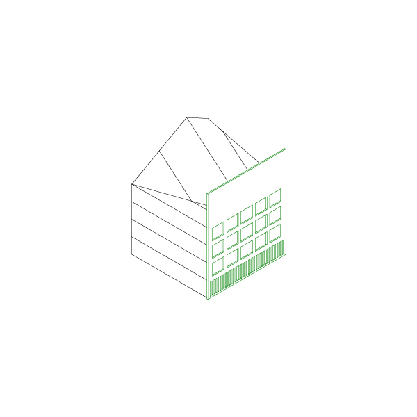


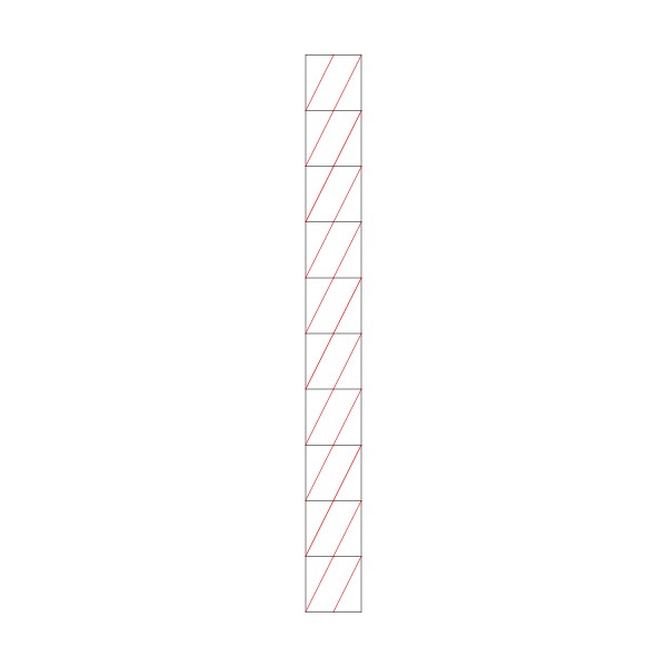

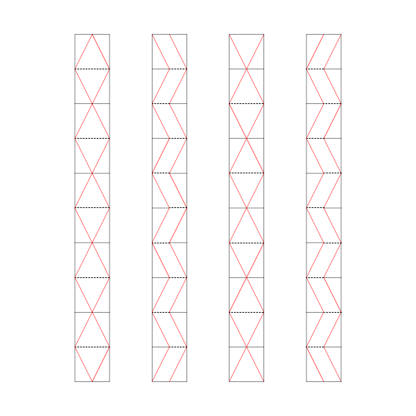


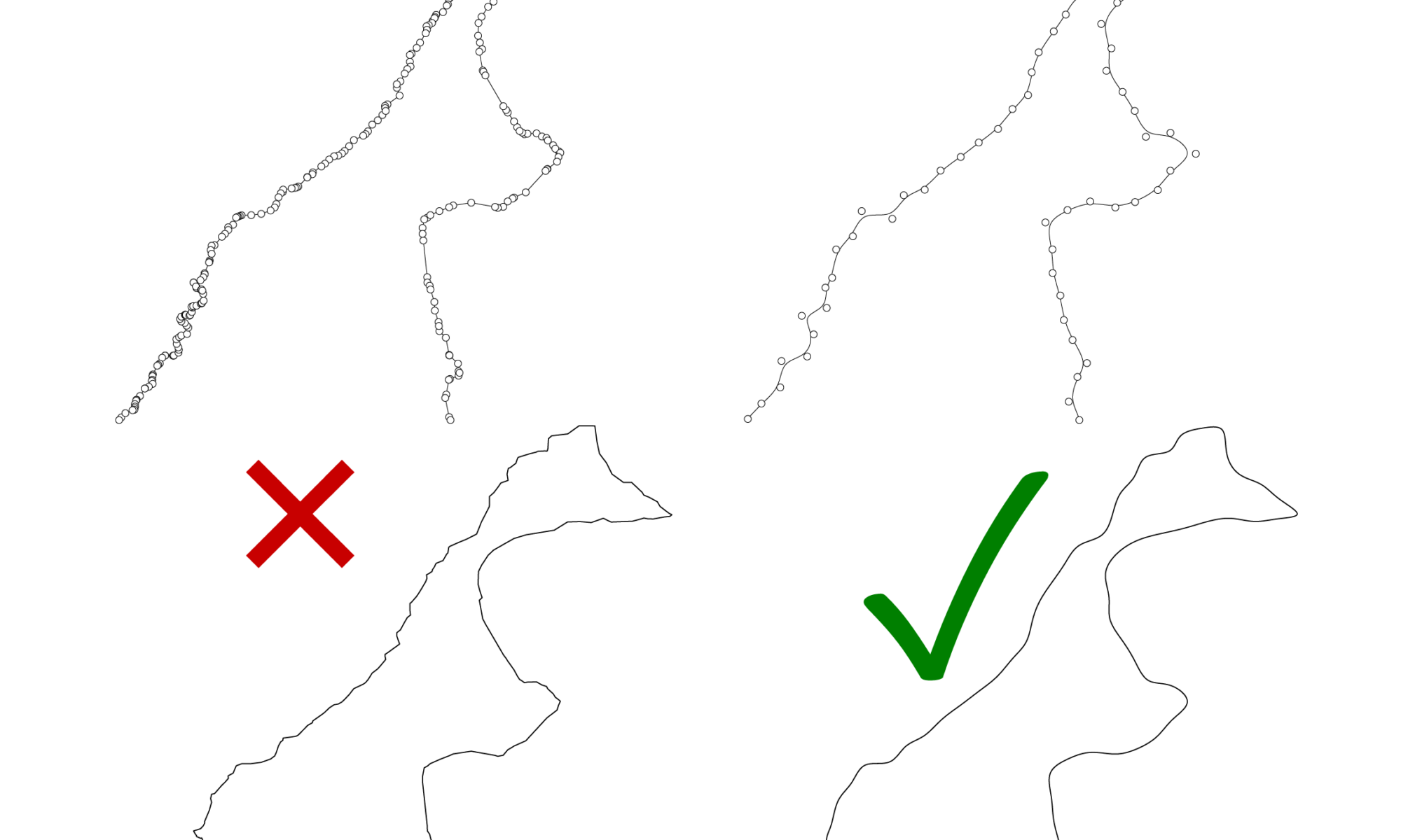
 Wrong.
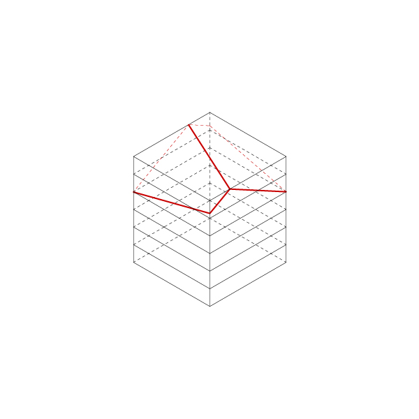
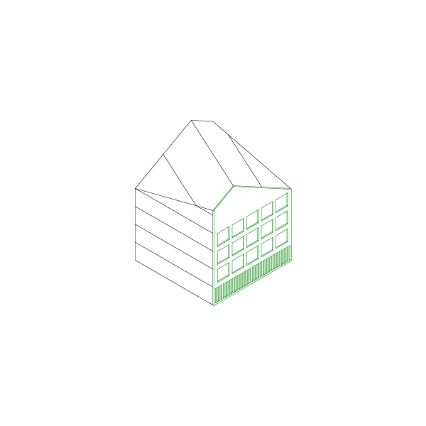
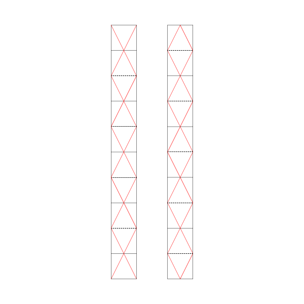
 Correct.
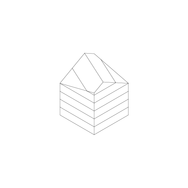