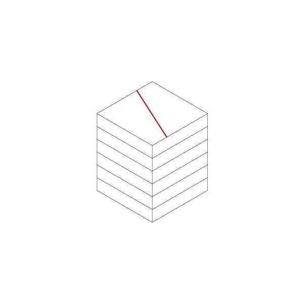
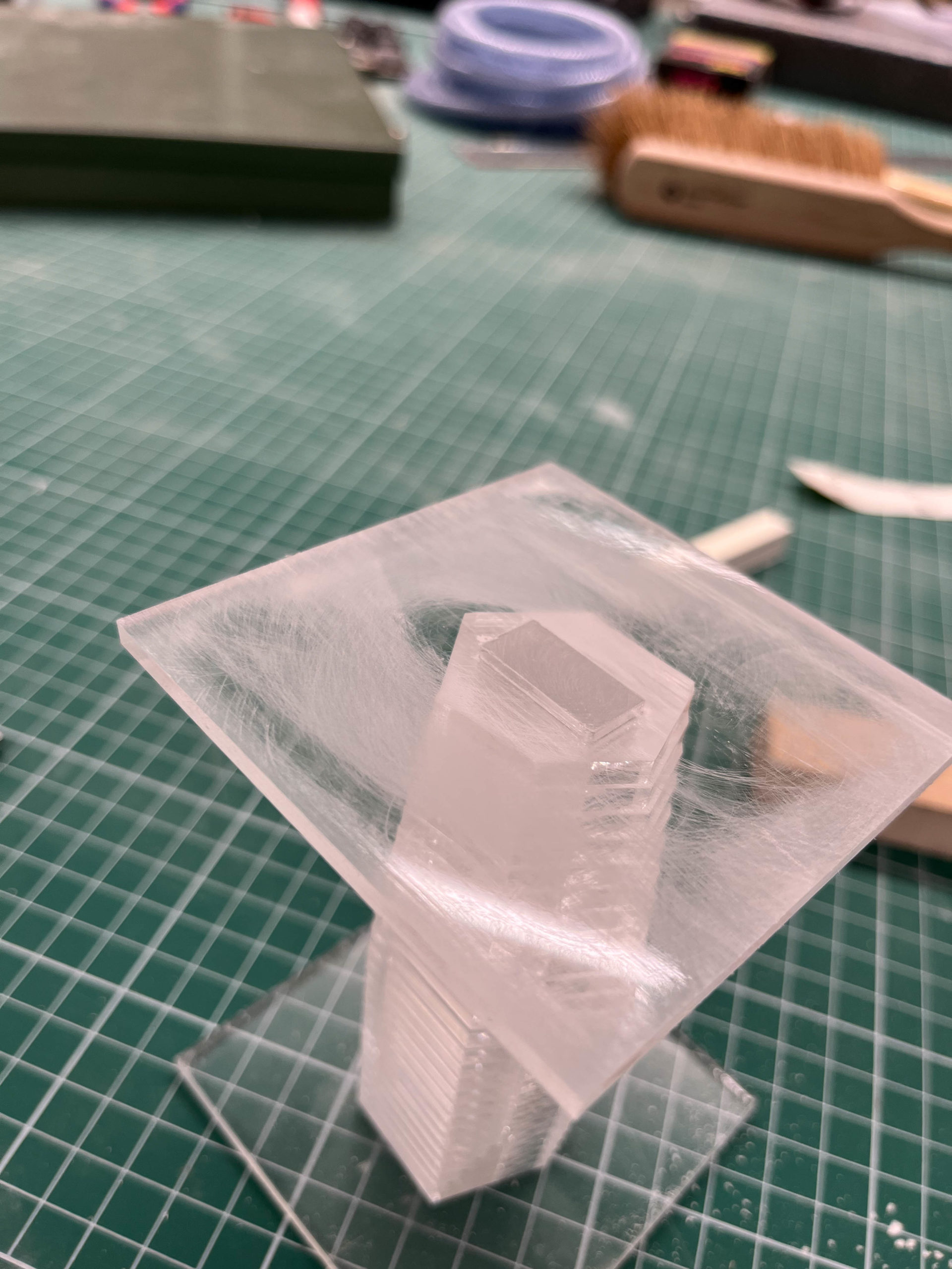
One of the principal considerations in 3d-printing architectural models is how to efficiently cut them before slicing. The technique presented here is a simple way to improve speed and success rates while maintaining an acceptable level of detail.
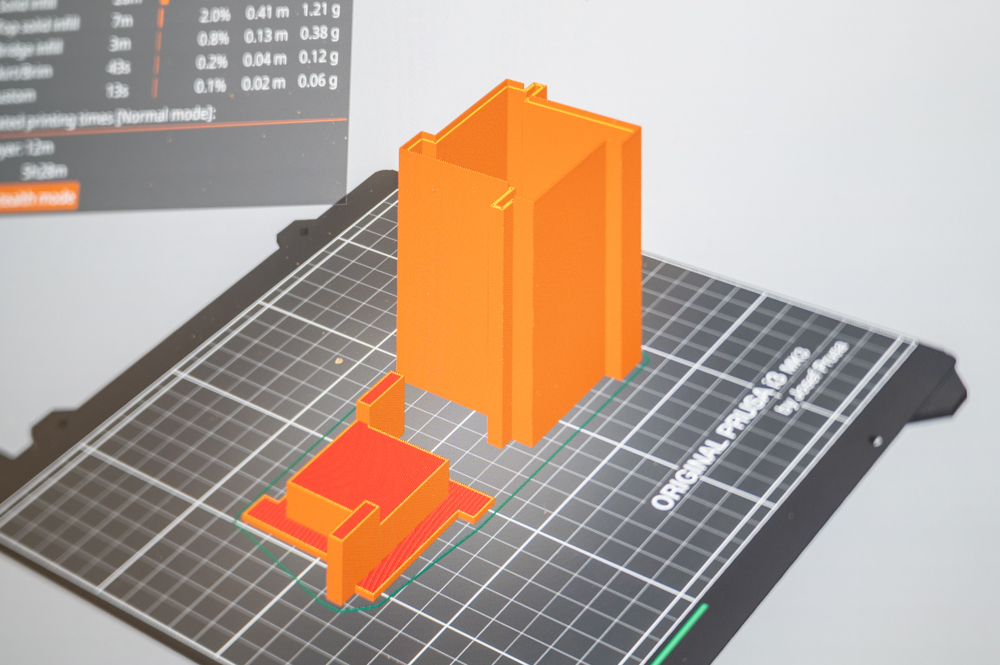
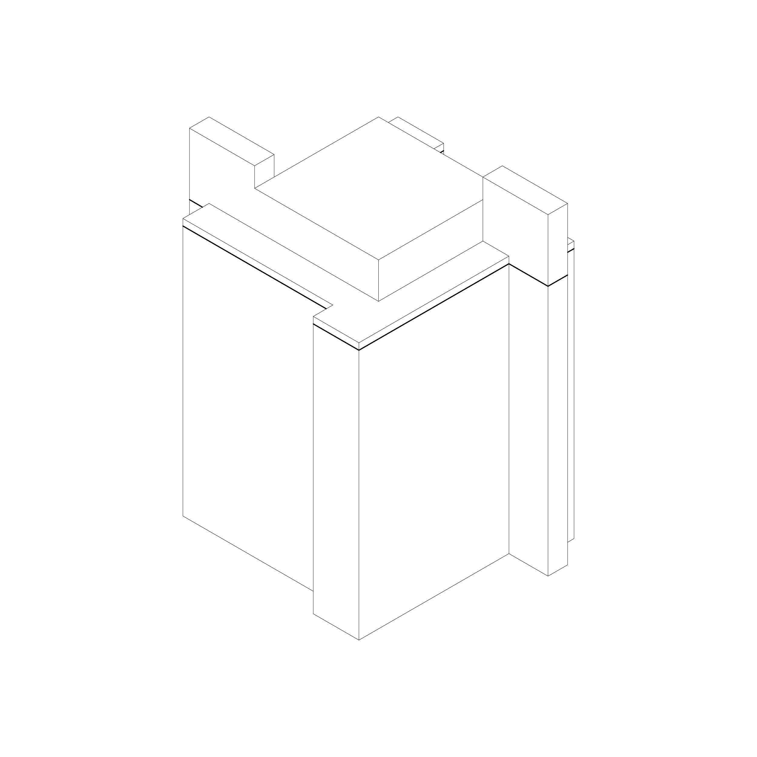
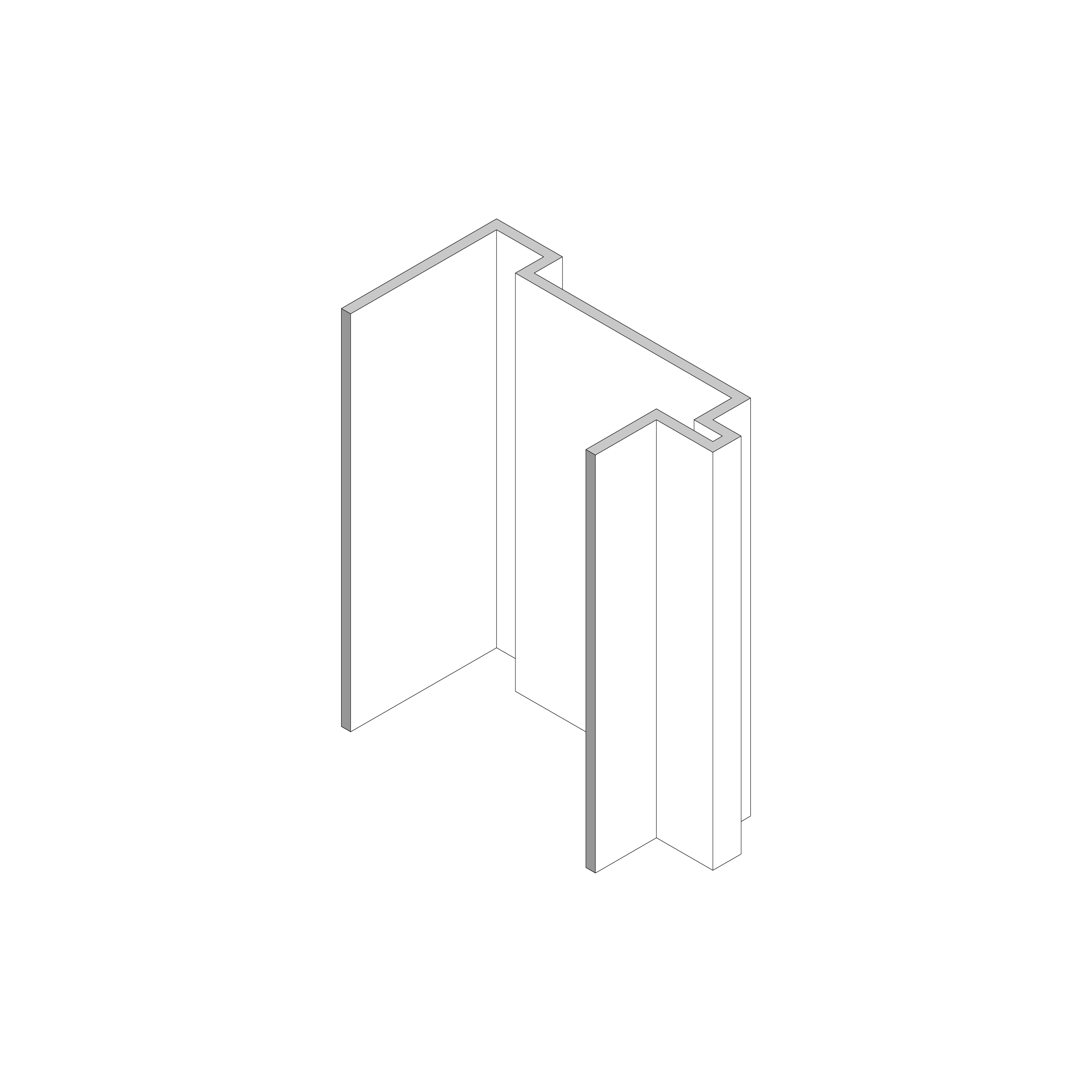
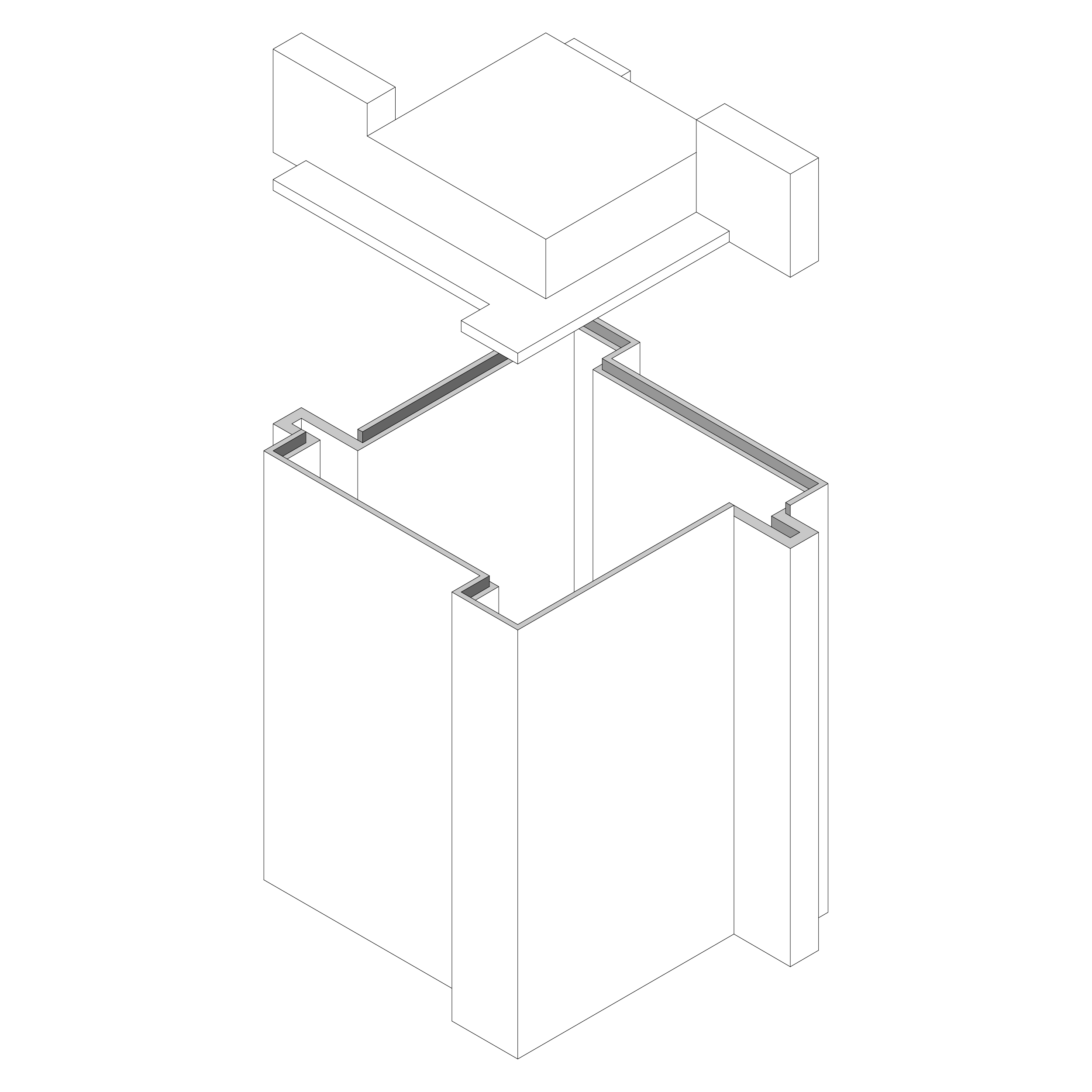
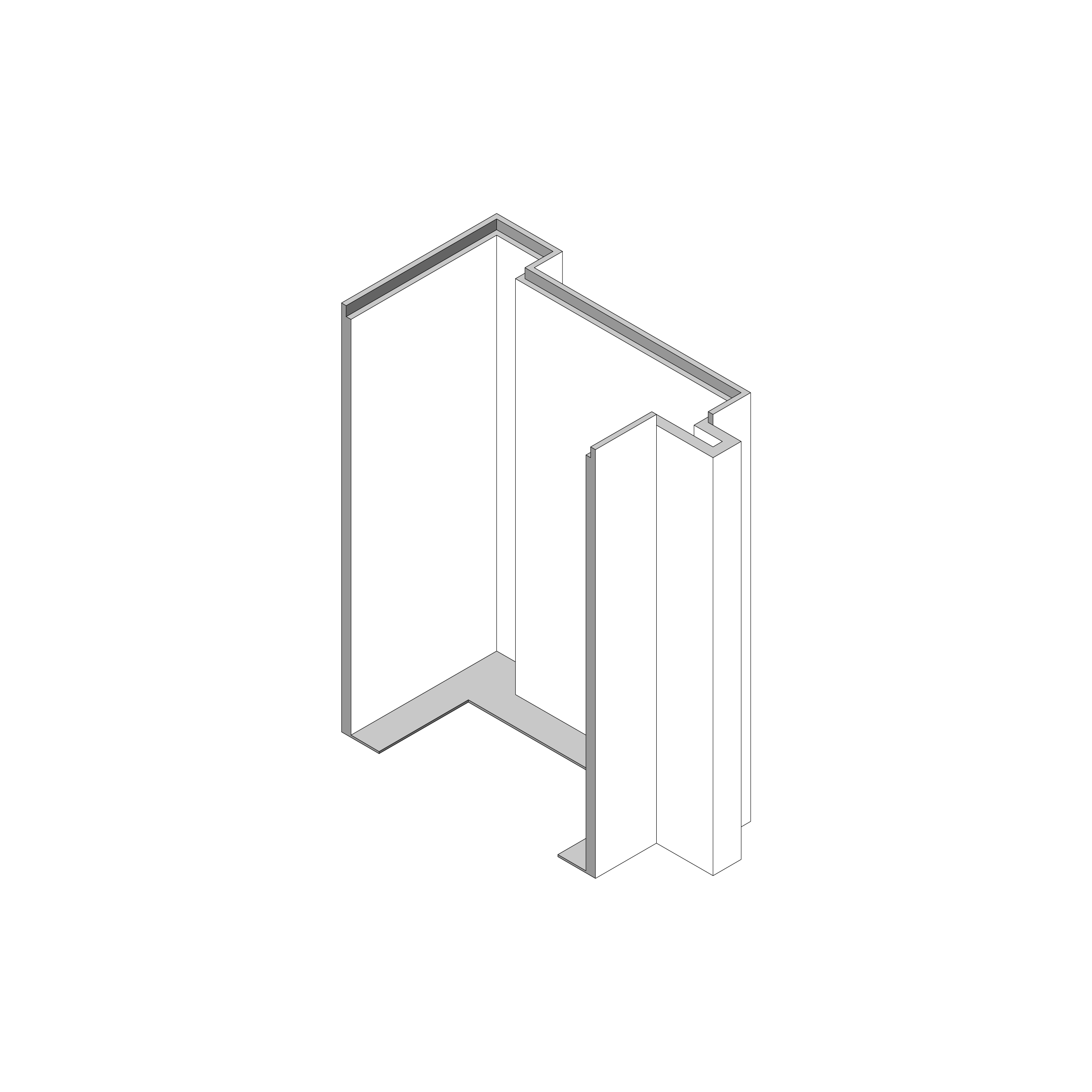
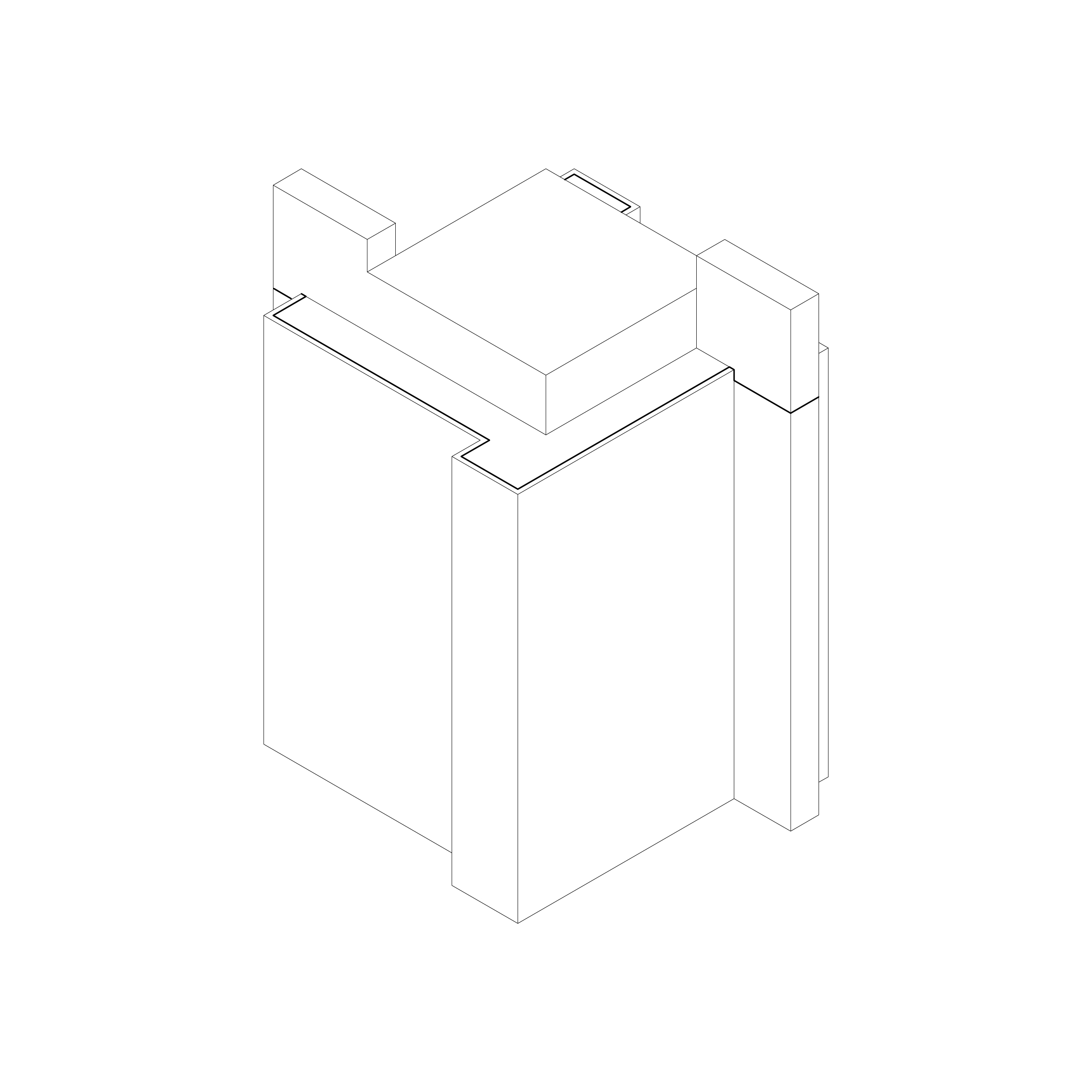
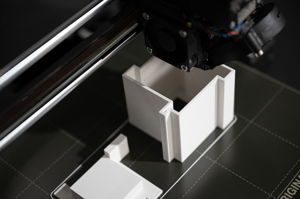
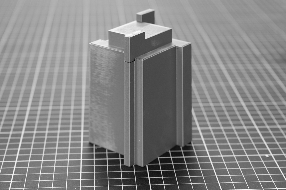
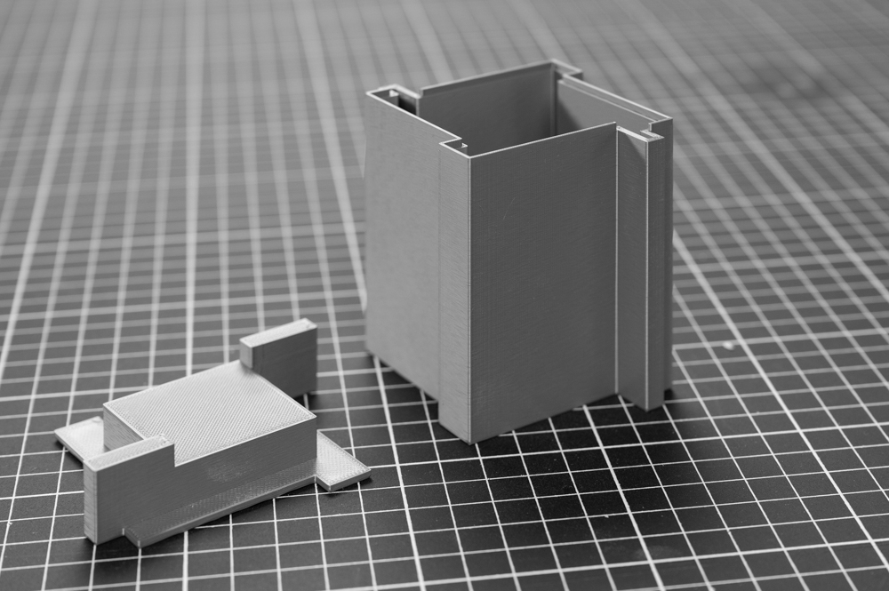
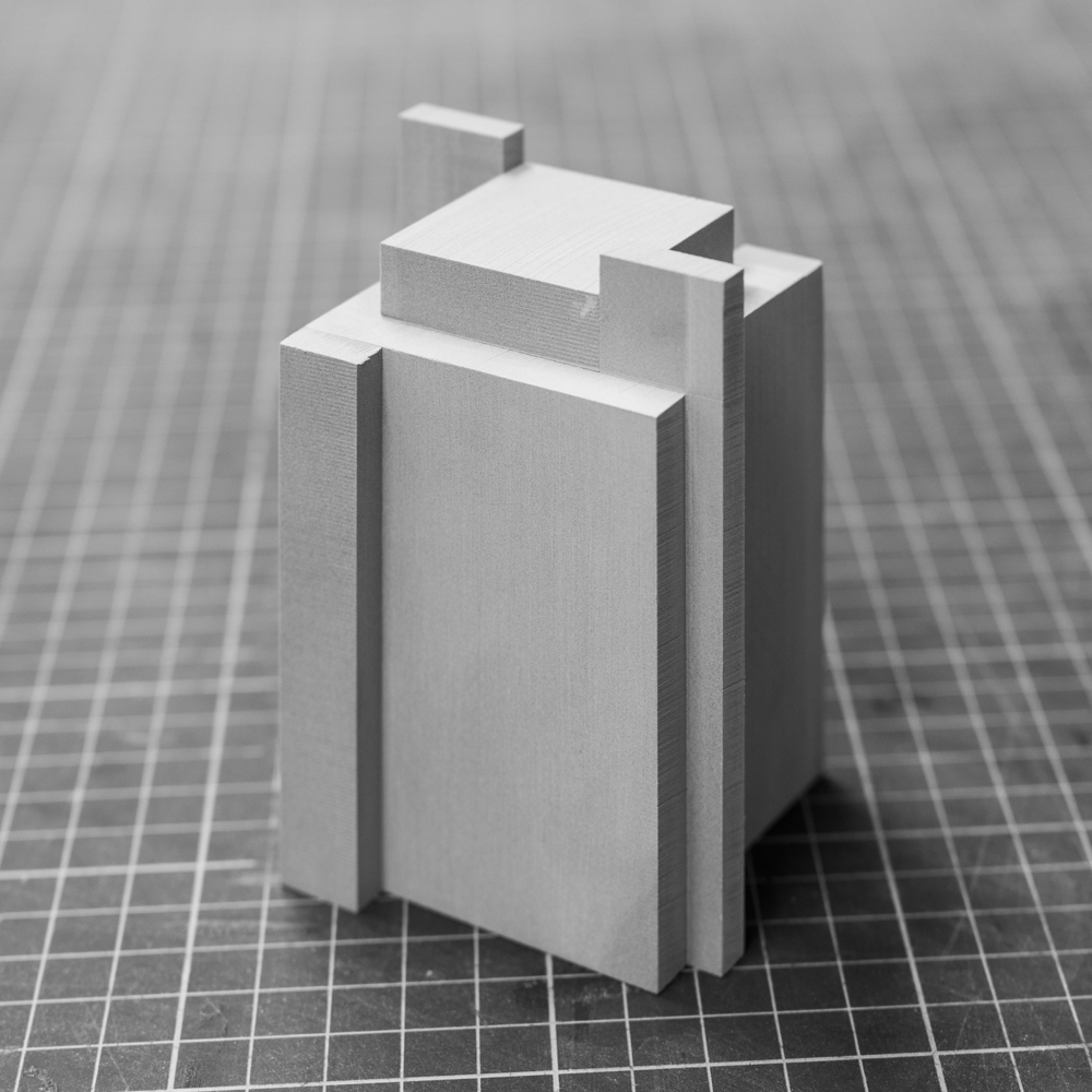
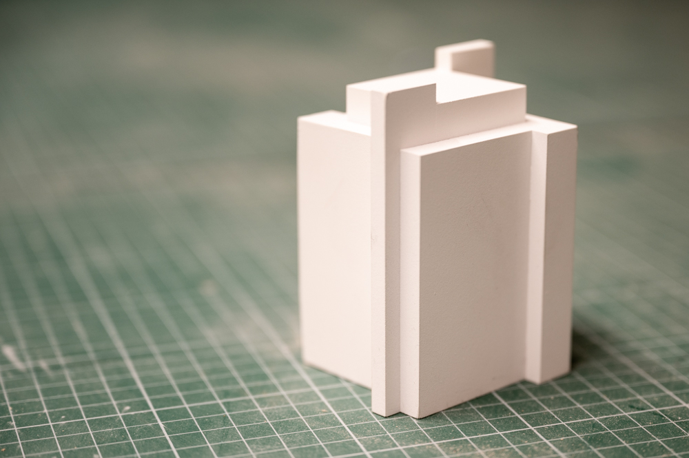
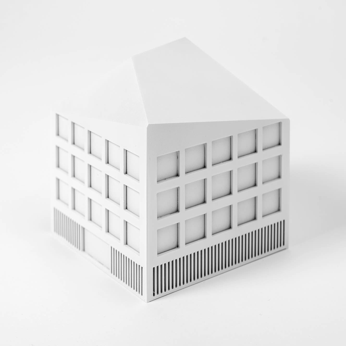
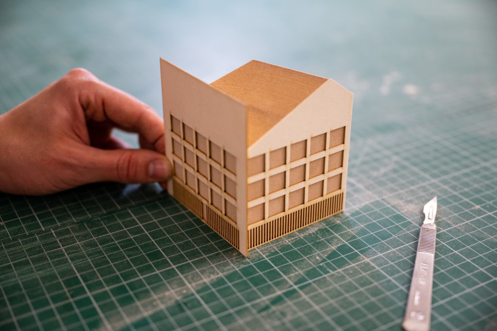
The principal idea is to separate the roof from the main body of the building so that the top acts as a lid. The body can then be hollow, consisting only of a wall, and prints drastically faster than a support-filled part.
Designing models for this sort of printing requires following some guidelines that have to do with the slicer and the diameter of the printer nozzle (typically 0.4mm).
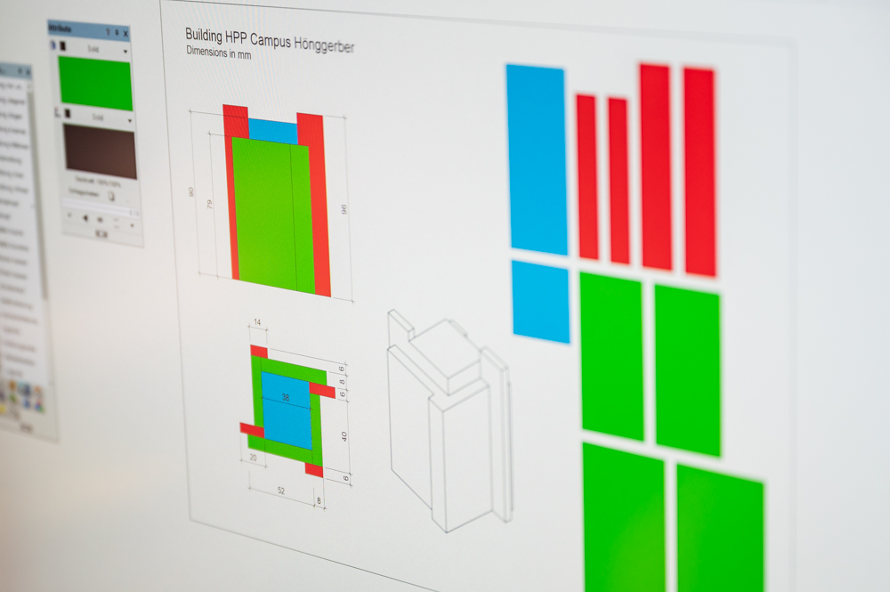
PrusaSlicer gives us the following recommendation under the parameter “vertical shells”:
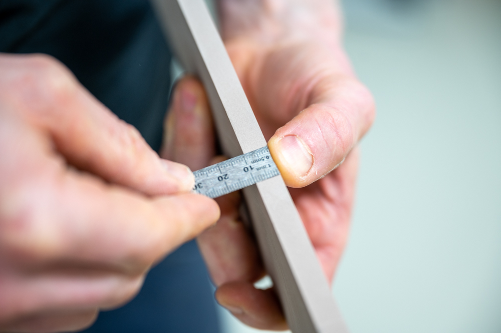
The model below was designed following these rules. The outer wall of the building is 1.67mm thick, and the small lip at the top that houses the roof is 0.86mm. All vertical extrusions try to stay within a 0.2mm grid corresponding to the layer height specified for this print. A 0.2mm layer at the bottom of the print for the wall part was introduced to ensure adequate adhesion on the build plate.
The top part was printed conventionally with 20% infill.
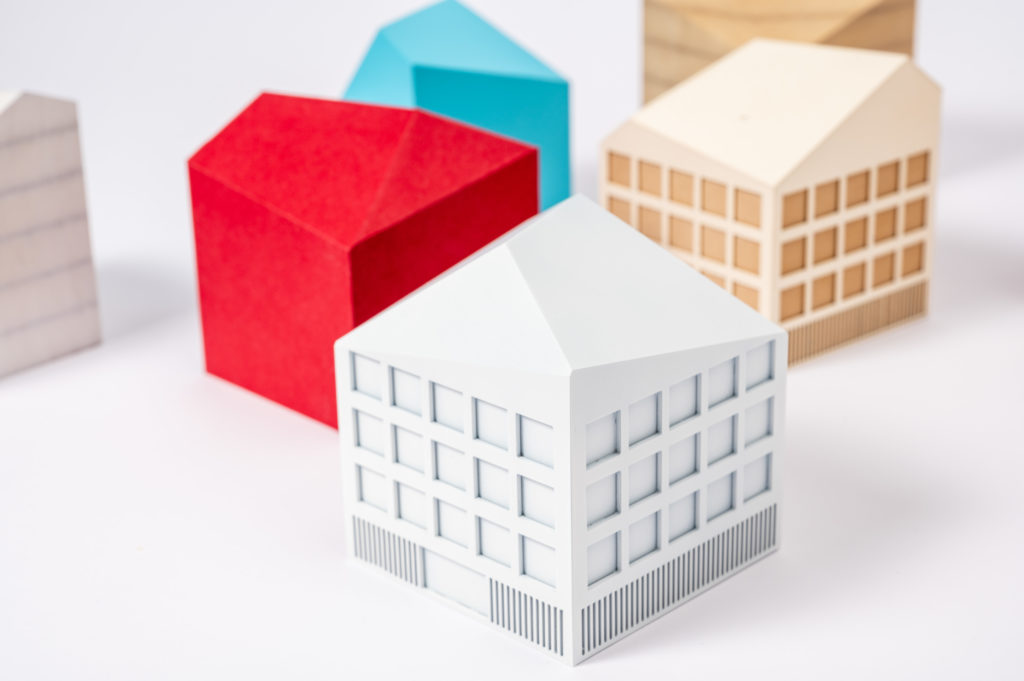
The total print time for this model has been reduced by half by applying these simple techniques while drawing the model.
Material
Polylactic Acid (PLA) is a thermosoft plastic polymer material that becomes pliable or moldable at elevated temperatures. The temperature range for 3d-printing is between 200-230°C with a bed temperature of 60°C to avoid warping.
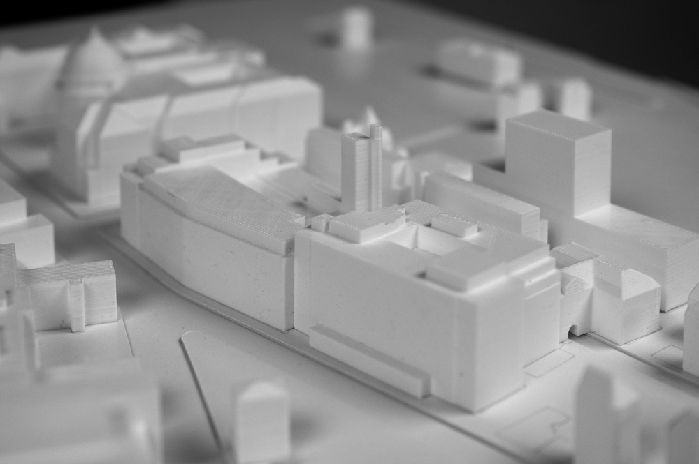
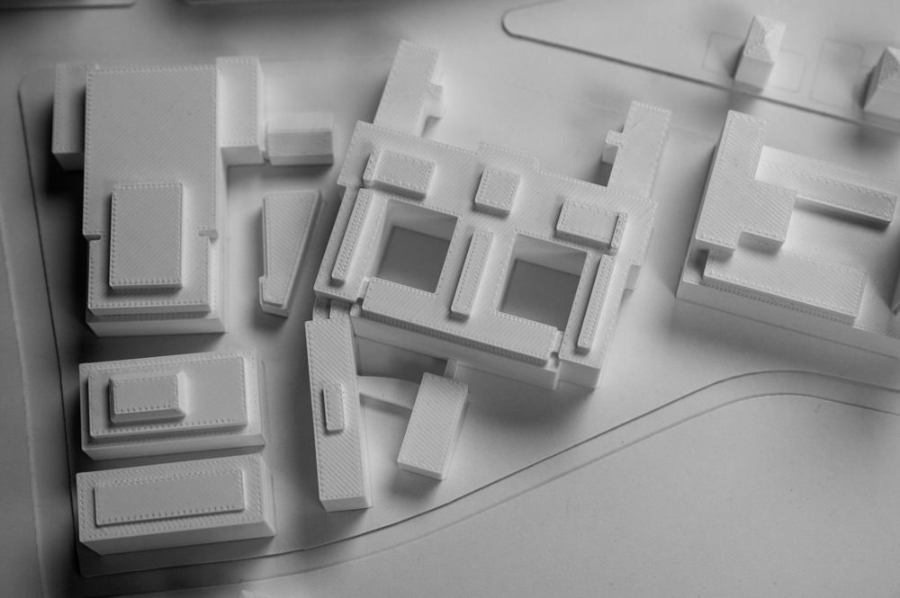
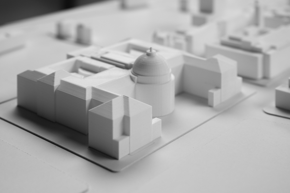
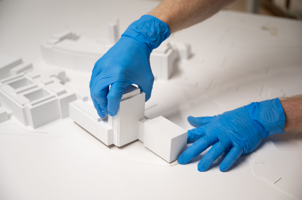
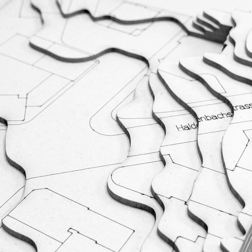
1:500 competition models and especially additions to those models are a fairly common topic in architectural model building. Understanding the fundamental principles of planning for such a model brings you a long way and can help to convey your project in the proper context.
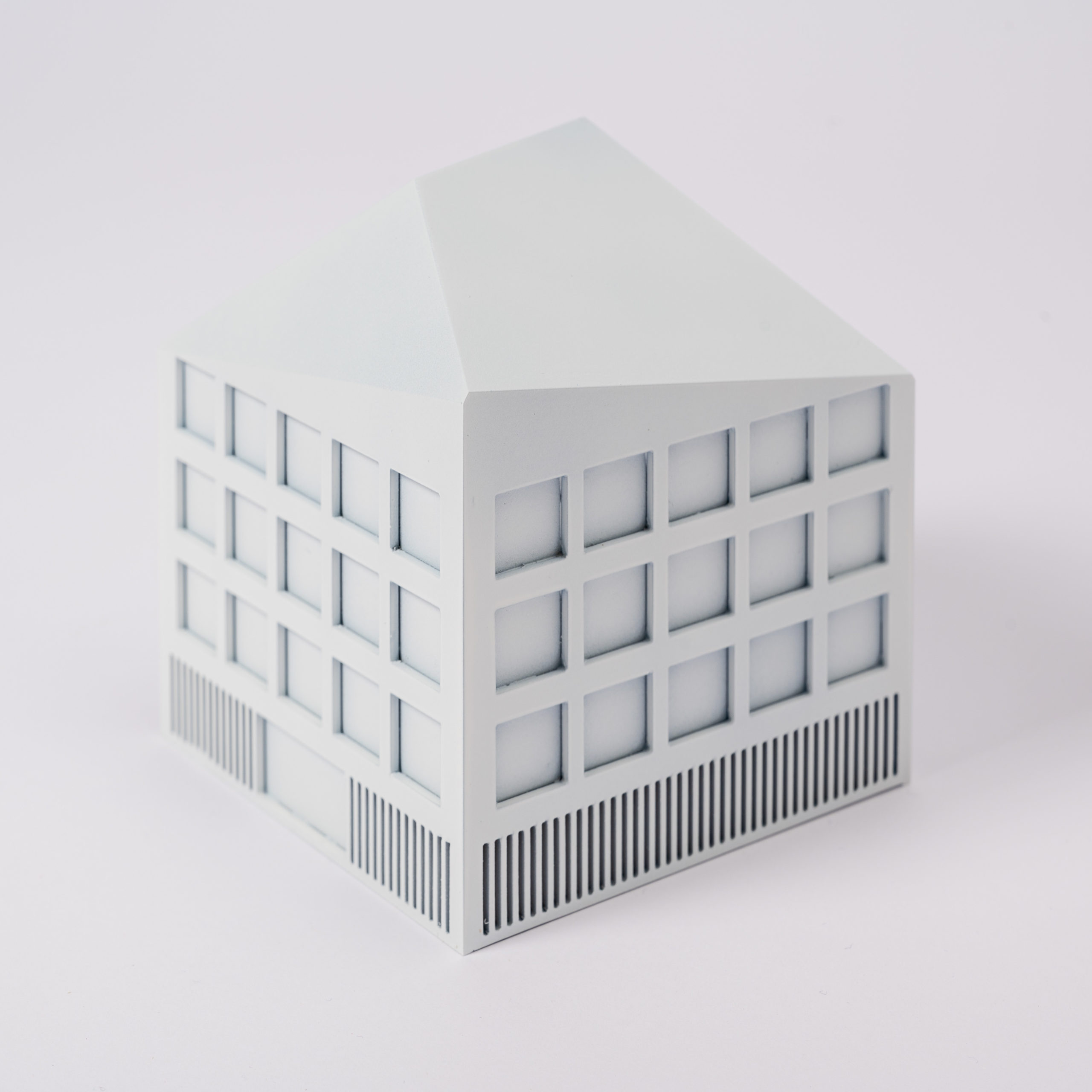
The white model is all about volumetric buildings and proportions. This model typology eliminates all other design aspects to give an “objectified” and comparable overview of a project. It is therefore imperative that details are reduced to only show the base volume of the building you want to build.
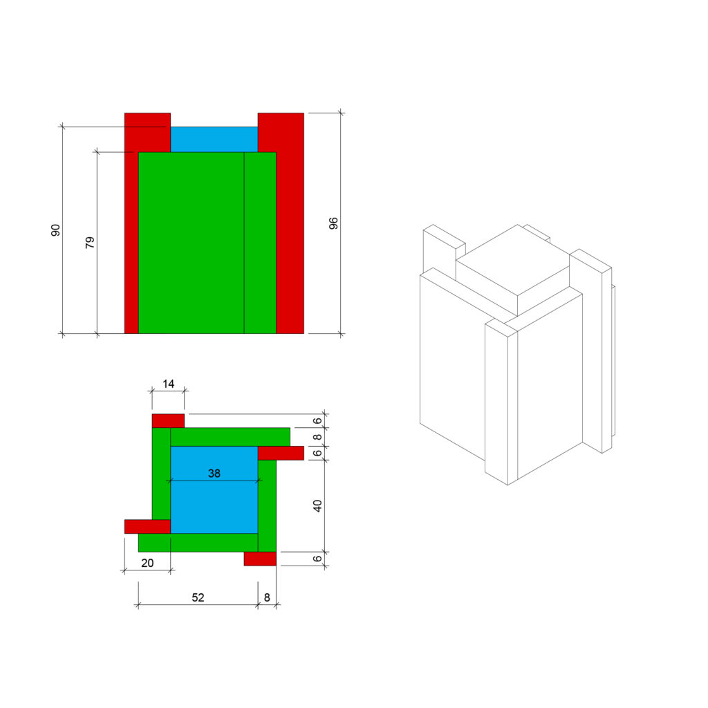
The first step in making these models is to analyze your essential volume and subdivide it into different parts. In this step, we typically try to round dimensions up or down to the full – or if not otherwise possible – half a millimeter. This facilitates the actual building process and allows using materials with specific thicknesses. This additional planning goes a long way to making your model-building experience more efficient and pleasant.
Material
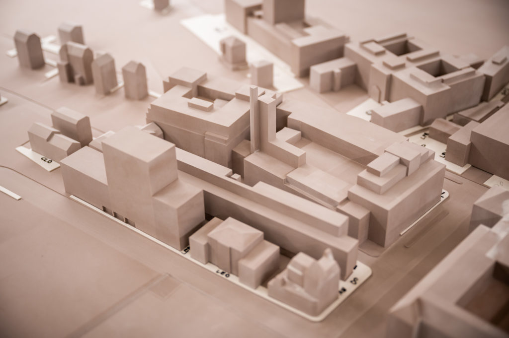
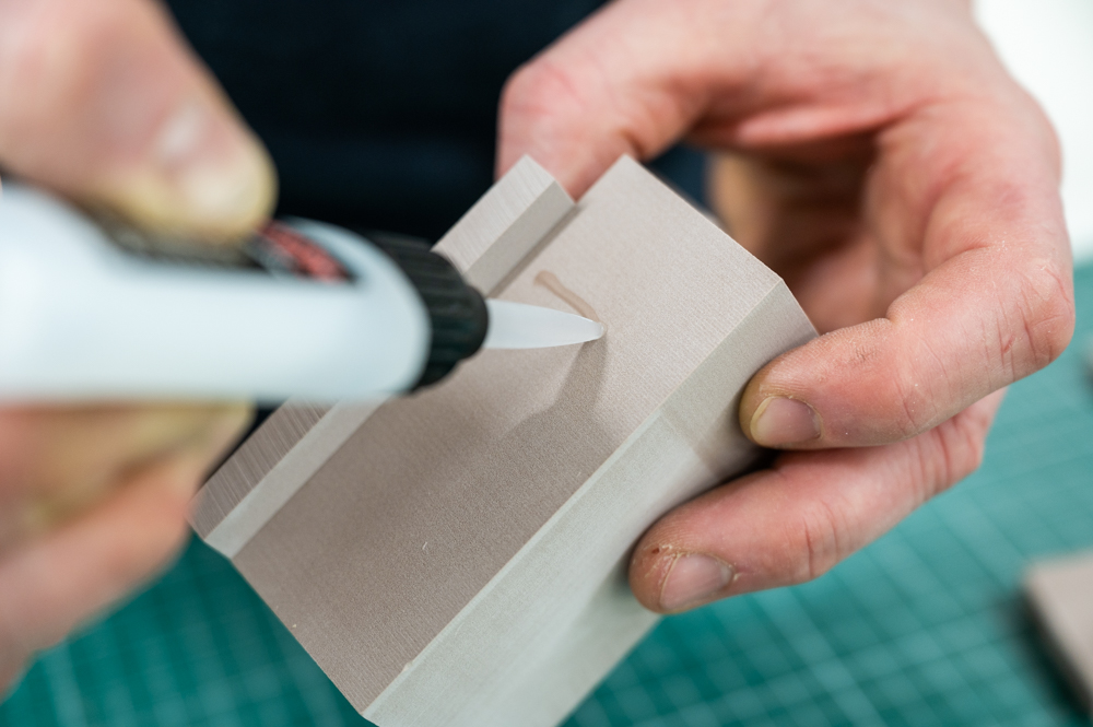
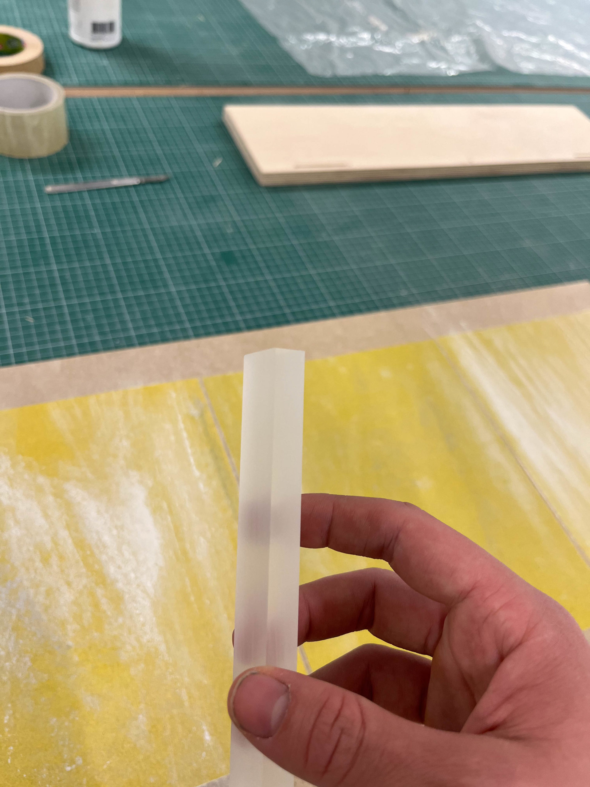
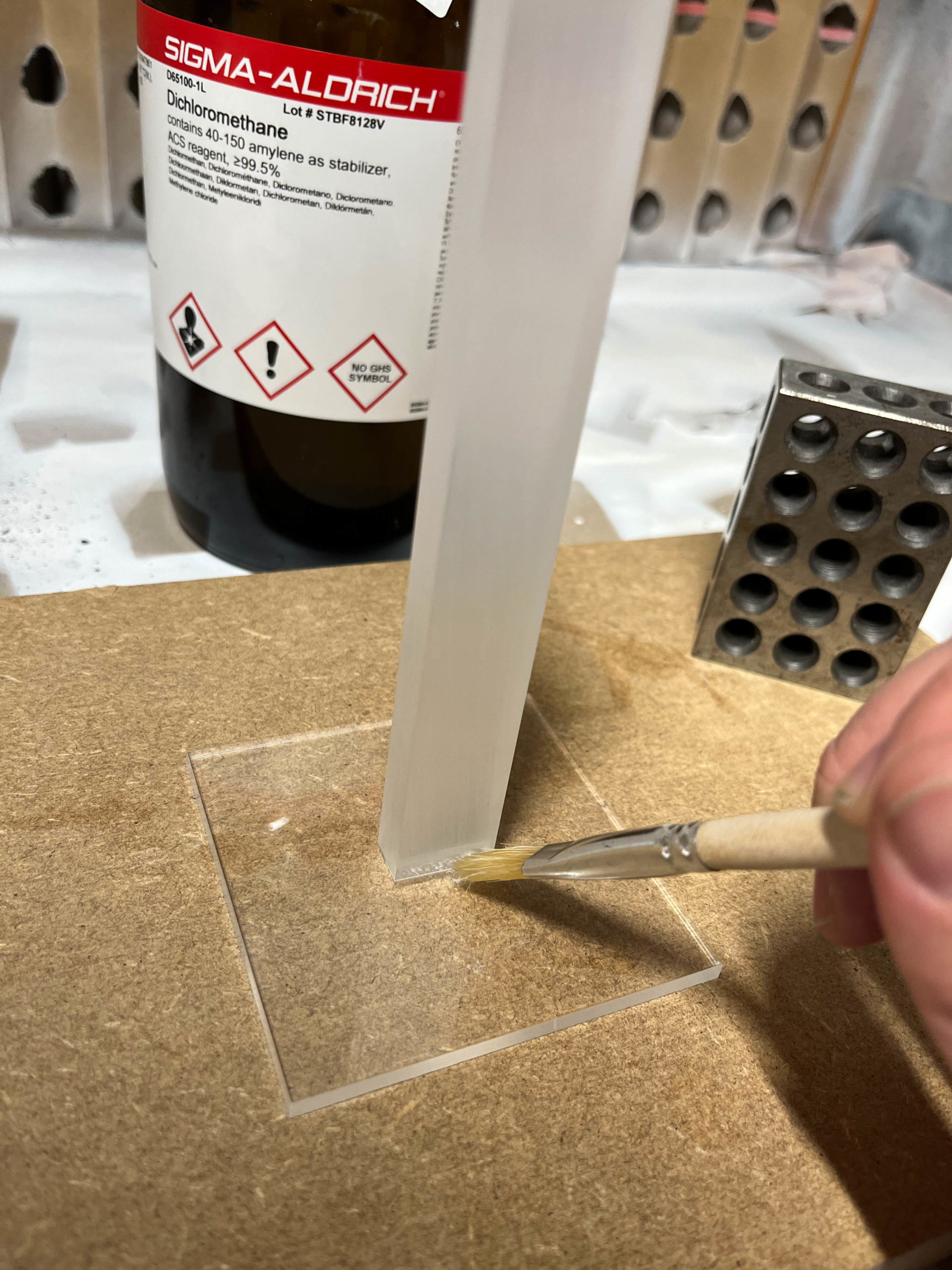
Various materials can be used to build 1:500 models, ranging from MDF and basswood to plaster or polystyrene. In our example, we used a type of PUR (Polyurethane) block material sold under many brand names worldwide (Ureol, Prolab, Raku-Tool, Renshape, …). Model builders choose the material because of its workability. It is easy to machine, sand, and glue and can take almost any finish.
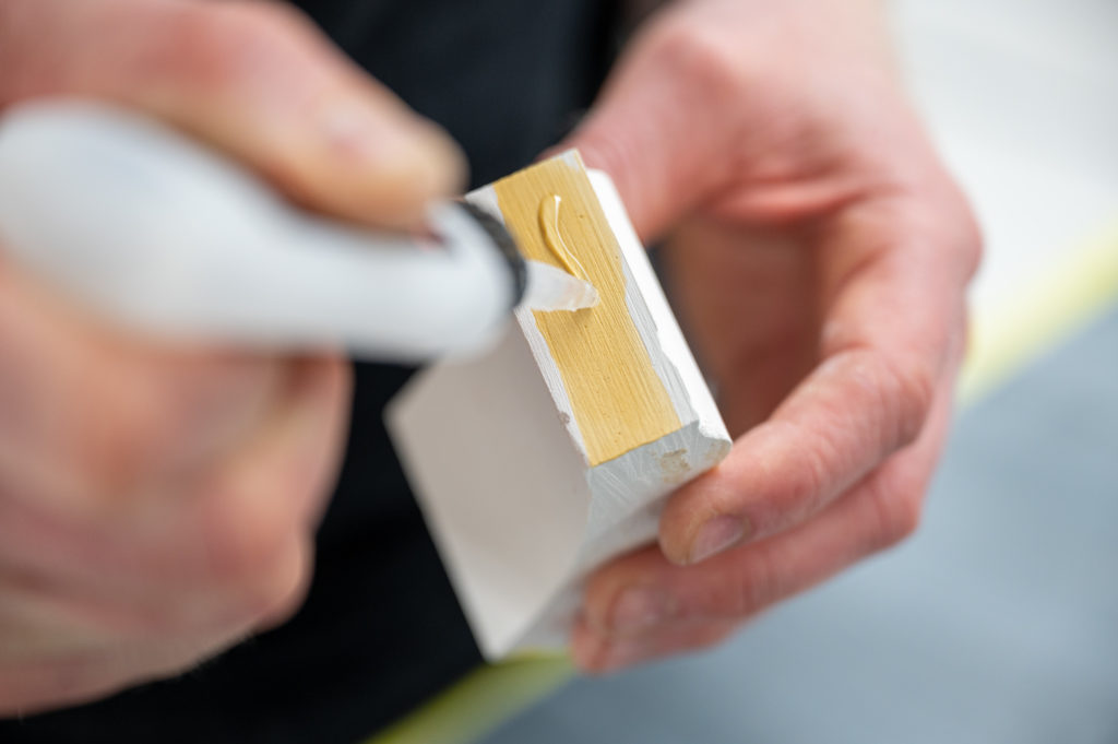
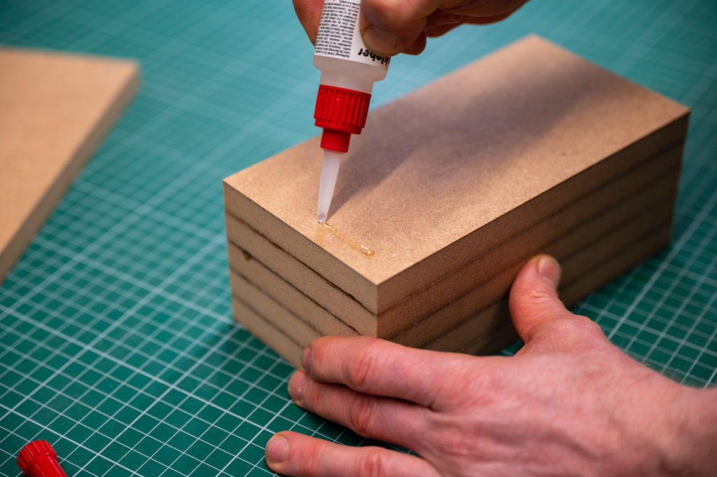
Raku-Tool has a density of 0.6g / cm3 and a shore hardness of 50-55. It can be used in the coated form as the final model or as the master for silicone forms. Joining two parts is quickly done with super glue, and gaps or imperfections can be filled with acrylic filler.
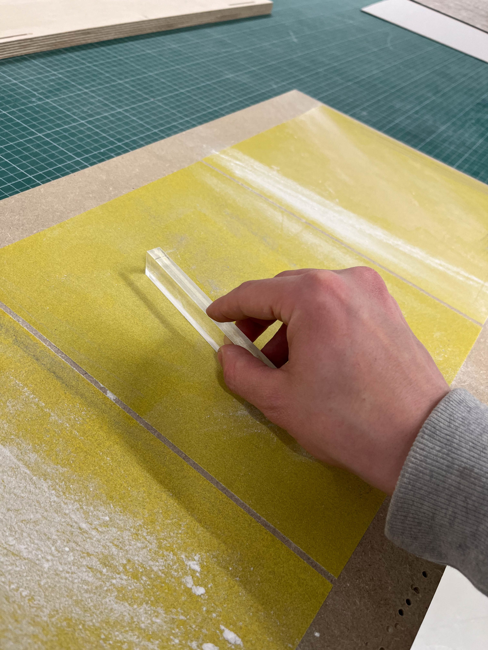
Technique
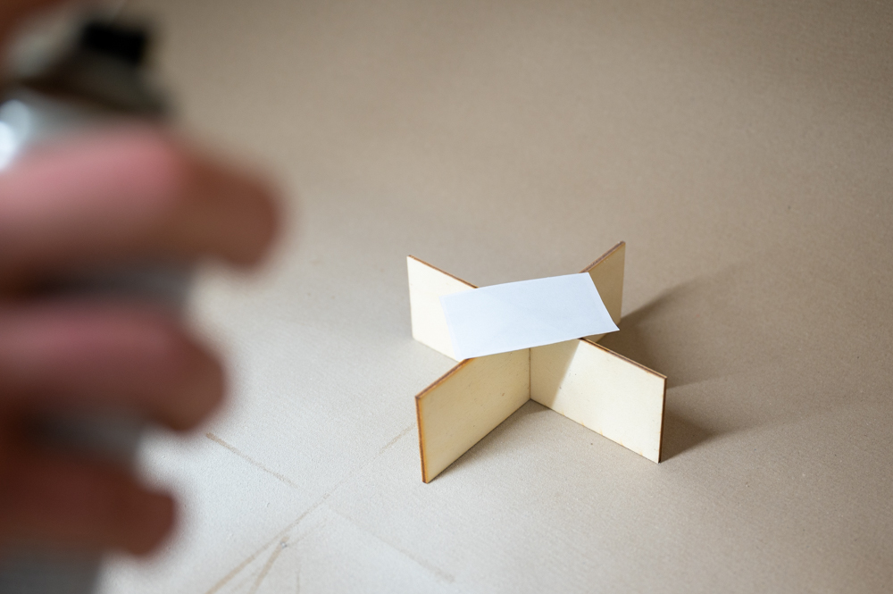
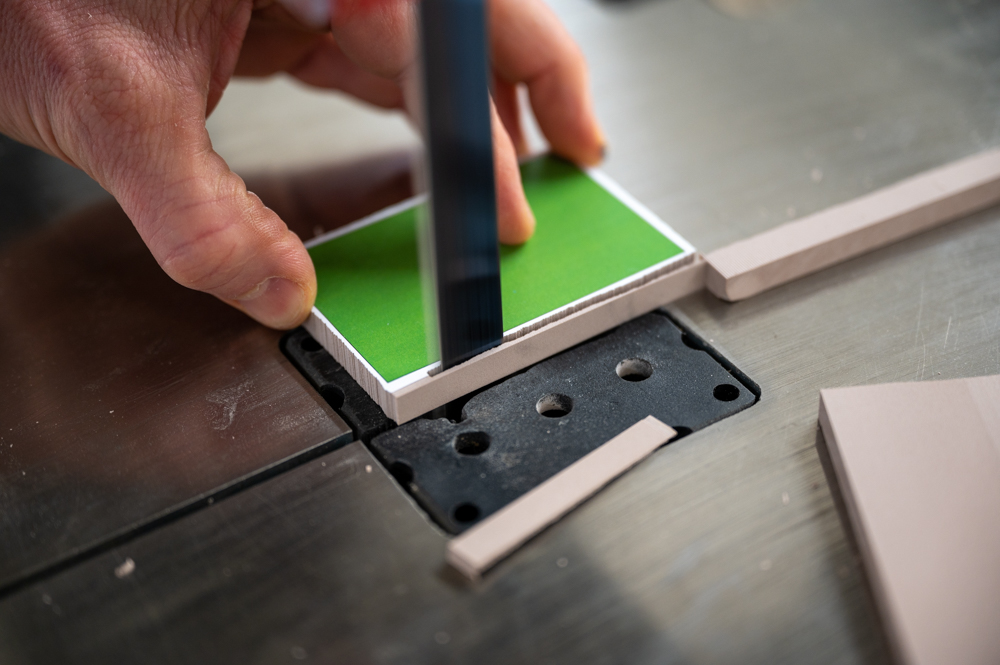
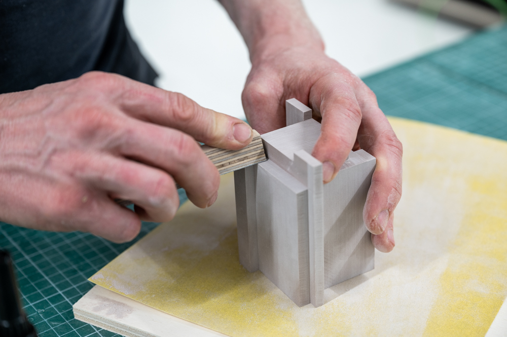
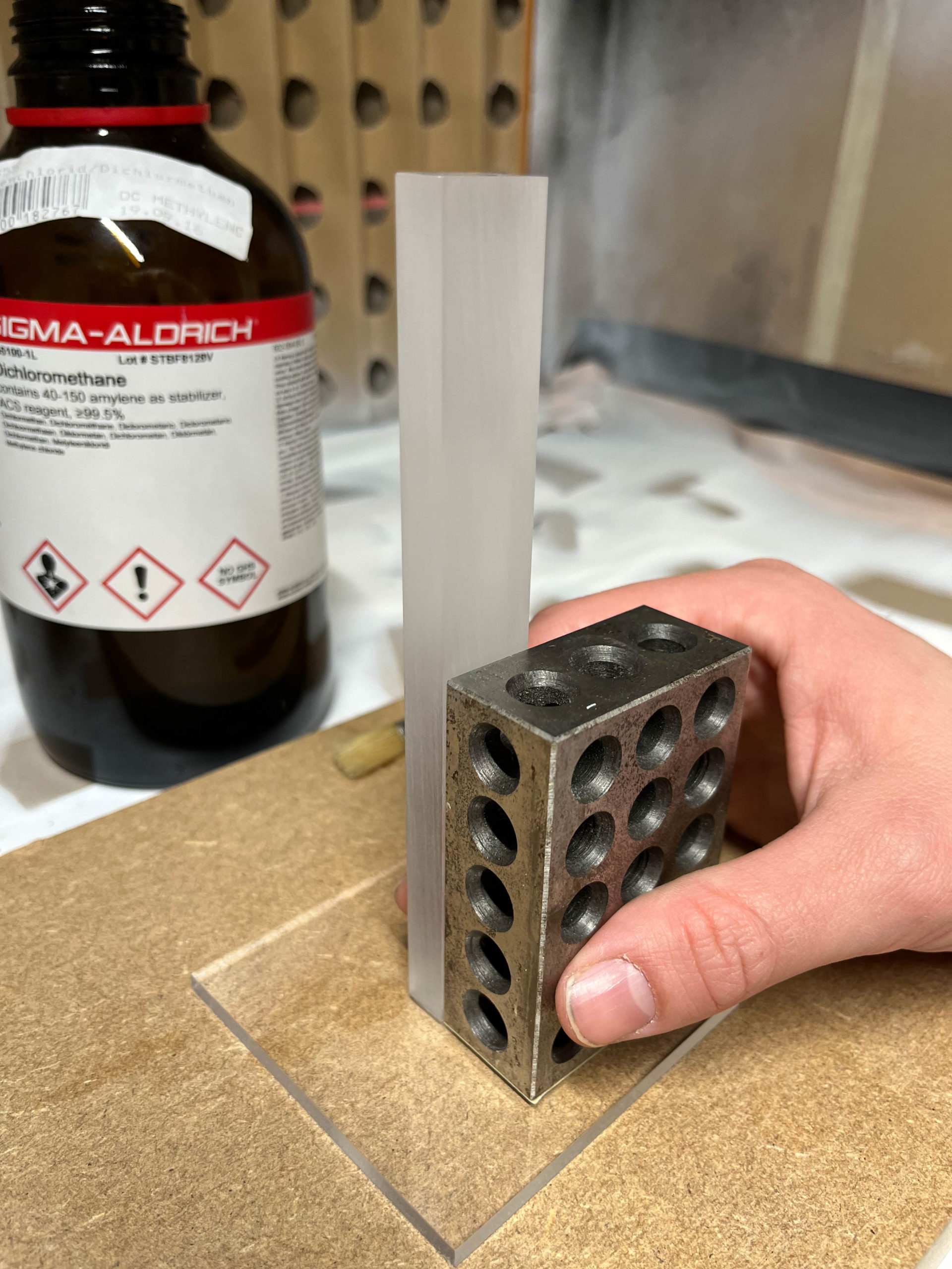
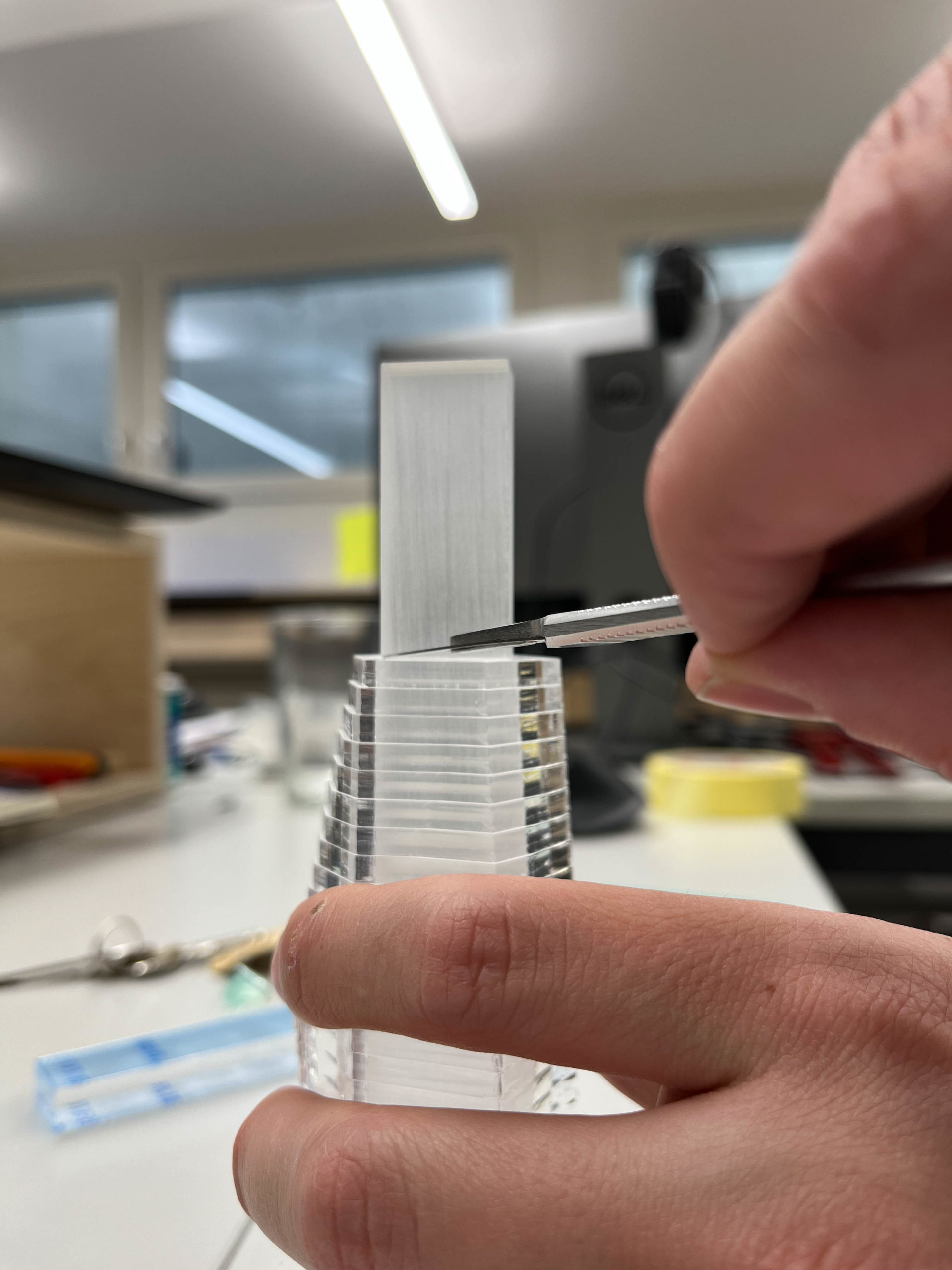
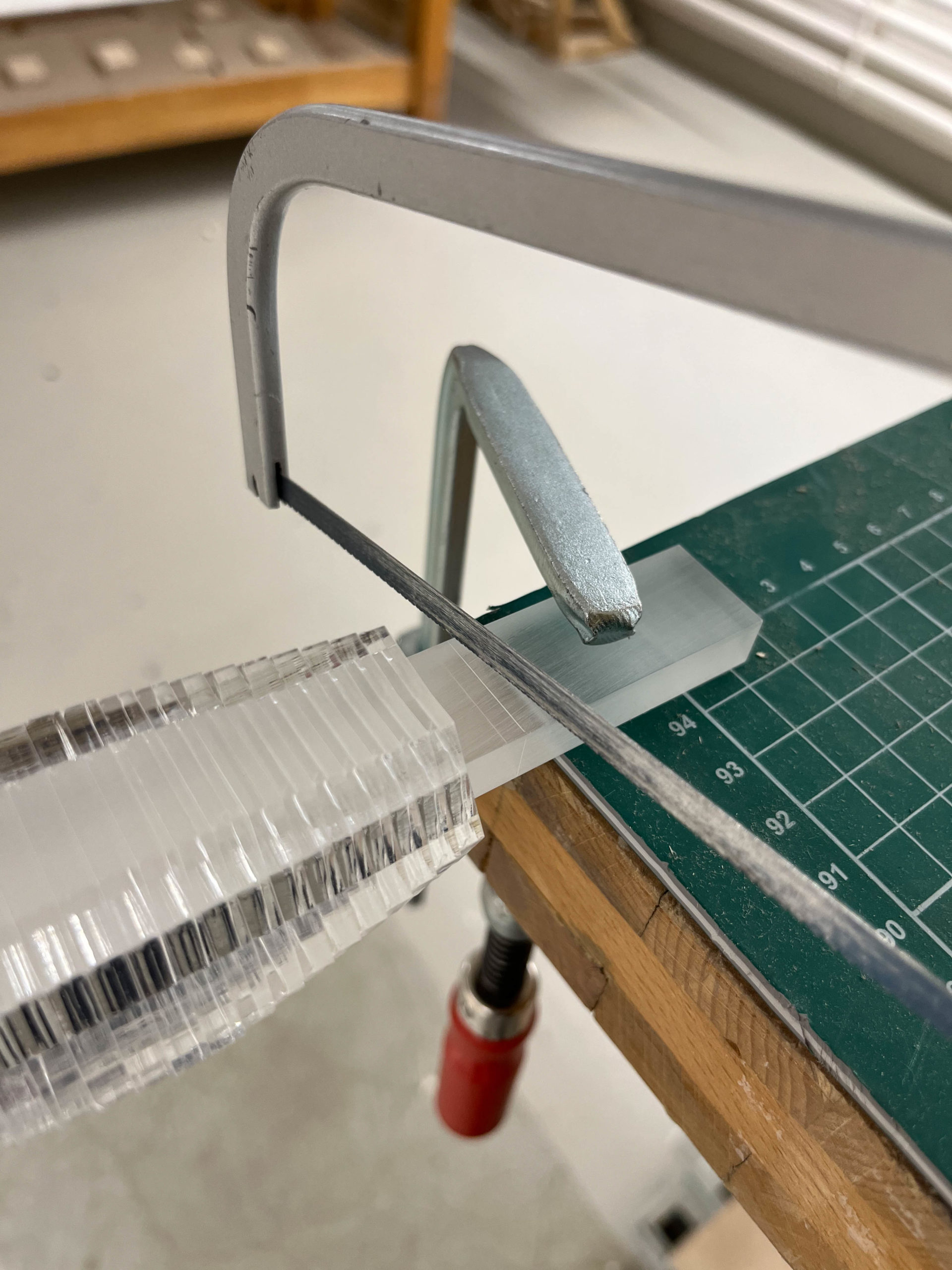
Building the model takes only a few simple steps that are repeated until all parts are finished and ready for assembly. We would like to point out that using the 3d-model to derive the surfaces and printing them as a template for producing parts is an essential technique that speeds up model-building and adds precision to your models. At this point, any preparation you’ve made during the modeling phase pays off its dividends. It typically shows in the details if the assembly logic of the model is simple and well understood. We hid some glue lines in the model by separating parts from the main body and covering the potential problem spots.
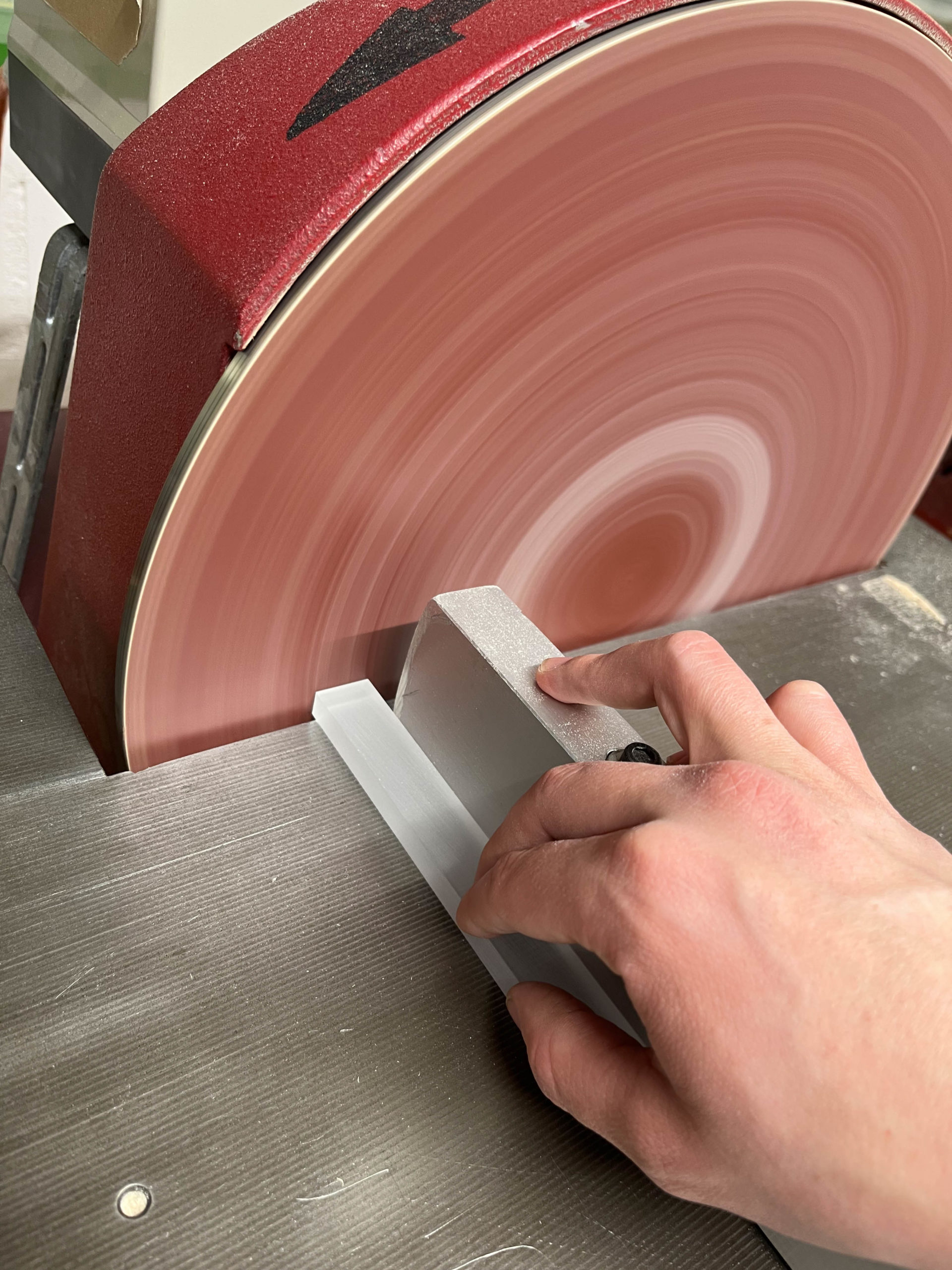
1. Create a simple 3d-model and subdivide it into parts 2. Cut your material on the bandsaw roughly into the different thicknesses needed for your project 3. Plane the material to the precise dimensions 4. Mount the templates with spray adhesive to your stock 5. Cut your parts to size, leaving a margin of approximately 1mm 6. Finish your parts on the disc sander 7. Assemble your parts according to your 3d-model ! Sand parts and surfaces that are difficult to reach (inside corners) first! 8. Make sure to sand your whole model with 220 grit to remove all marks from the disc sander 9. Finish your model with primer and top coat
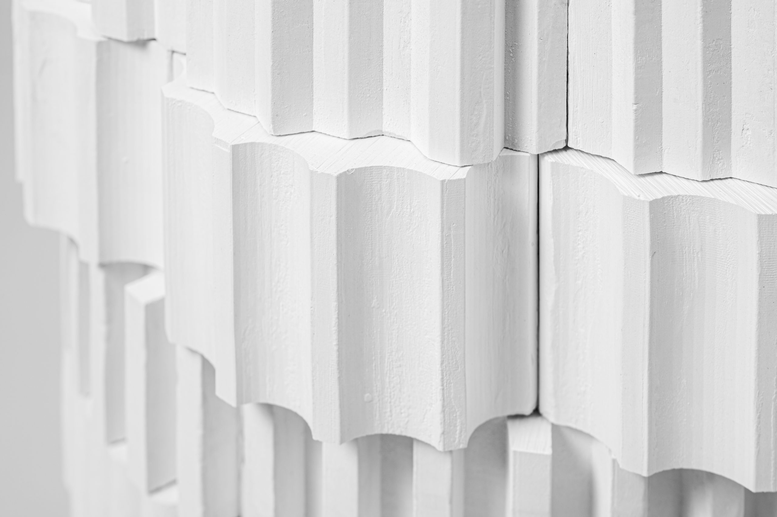
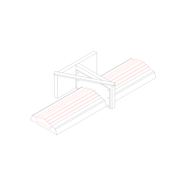
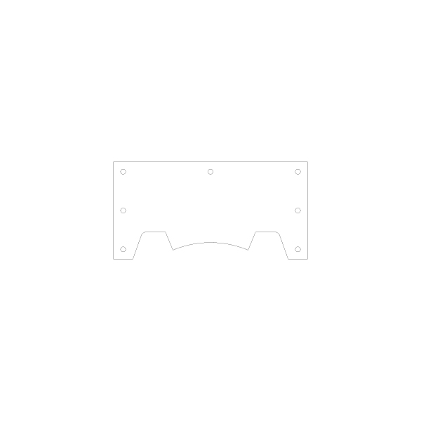
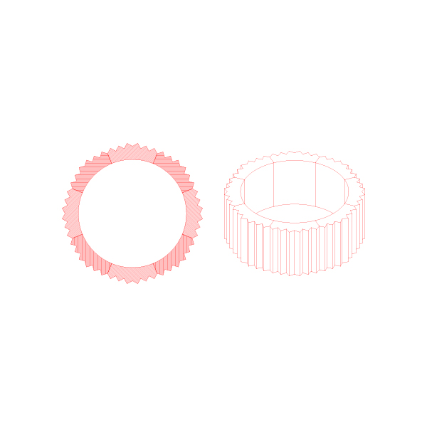
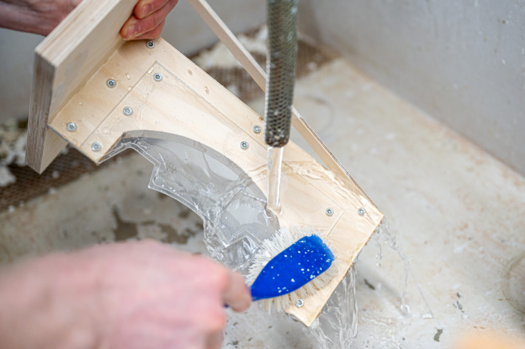
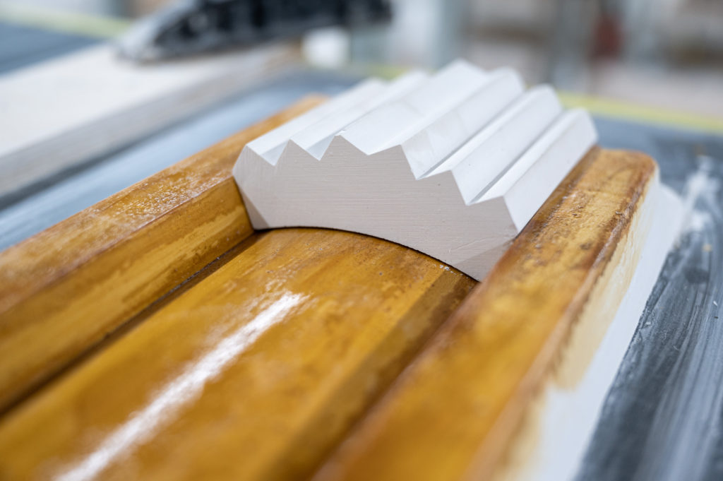
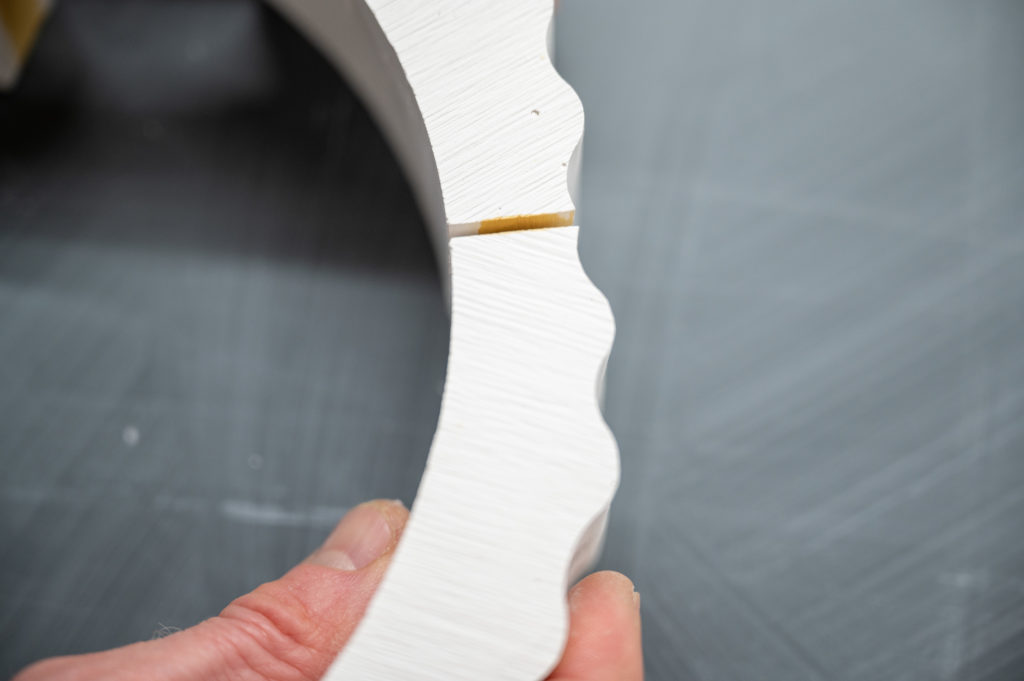
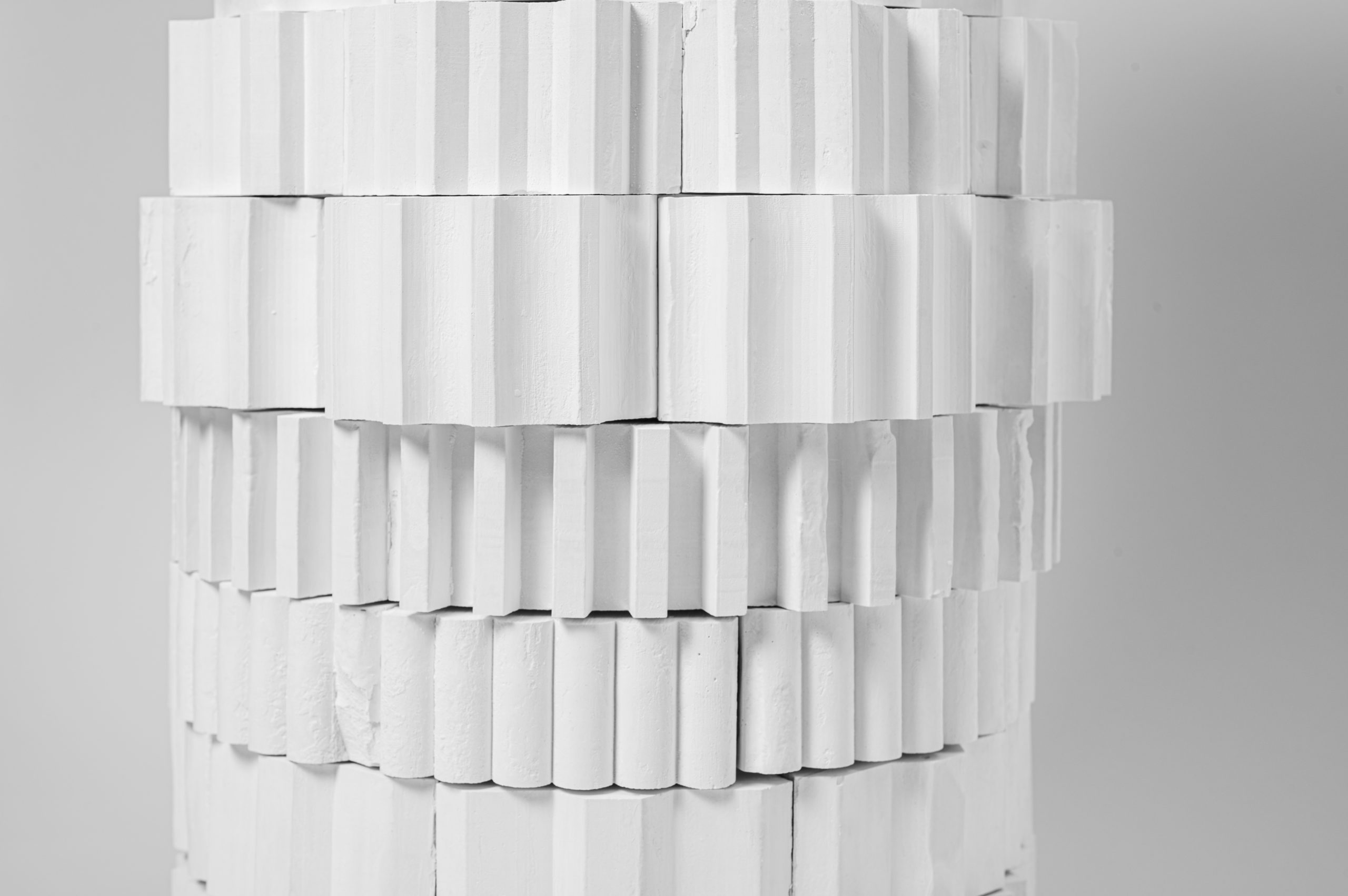
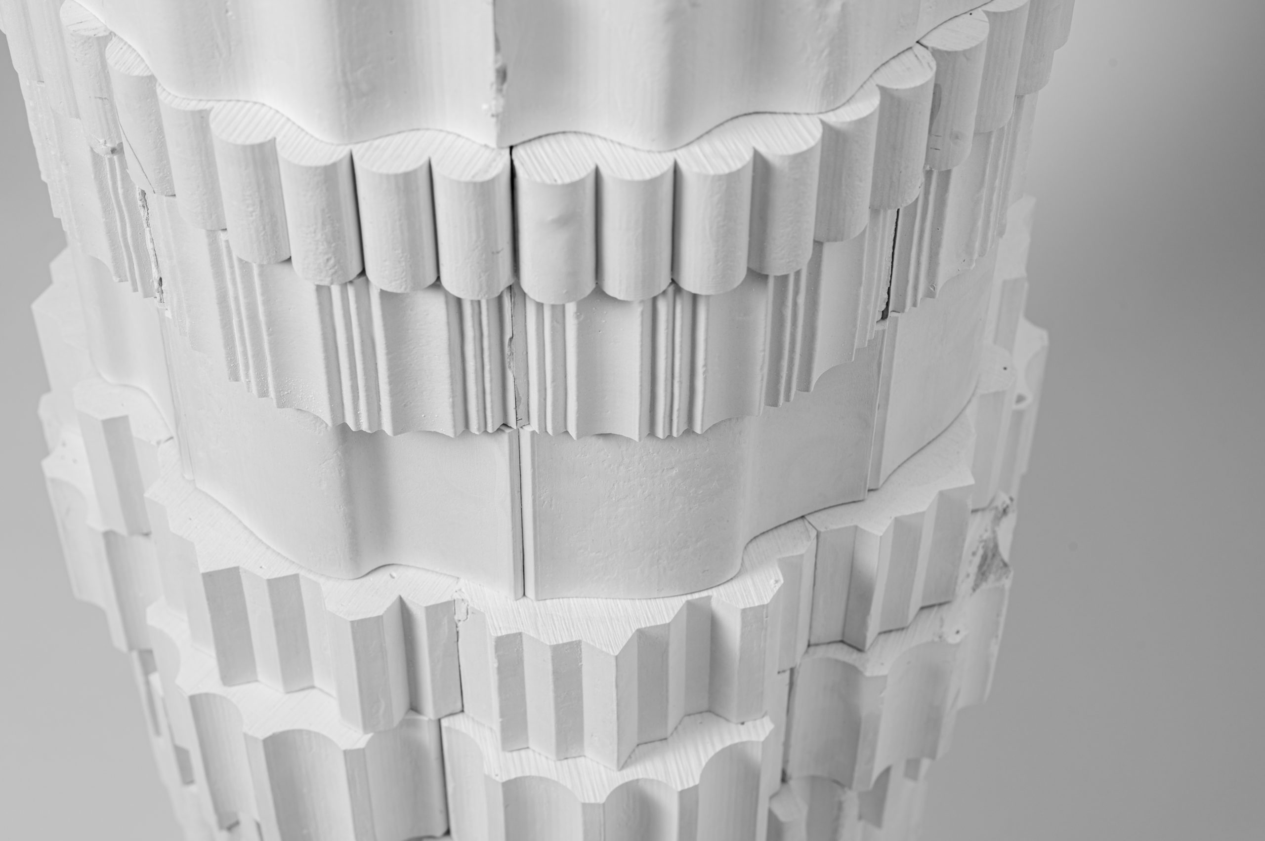
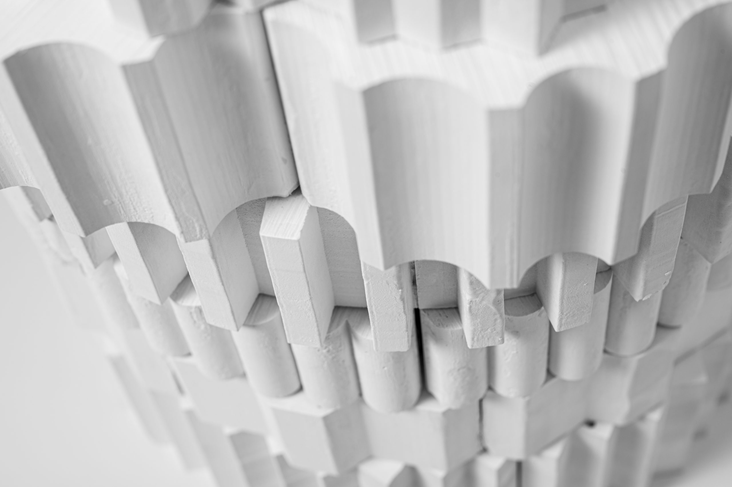
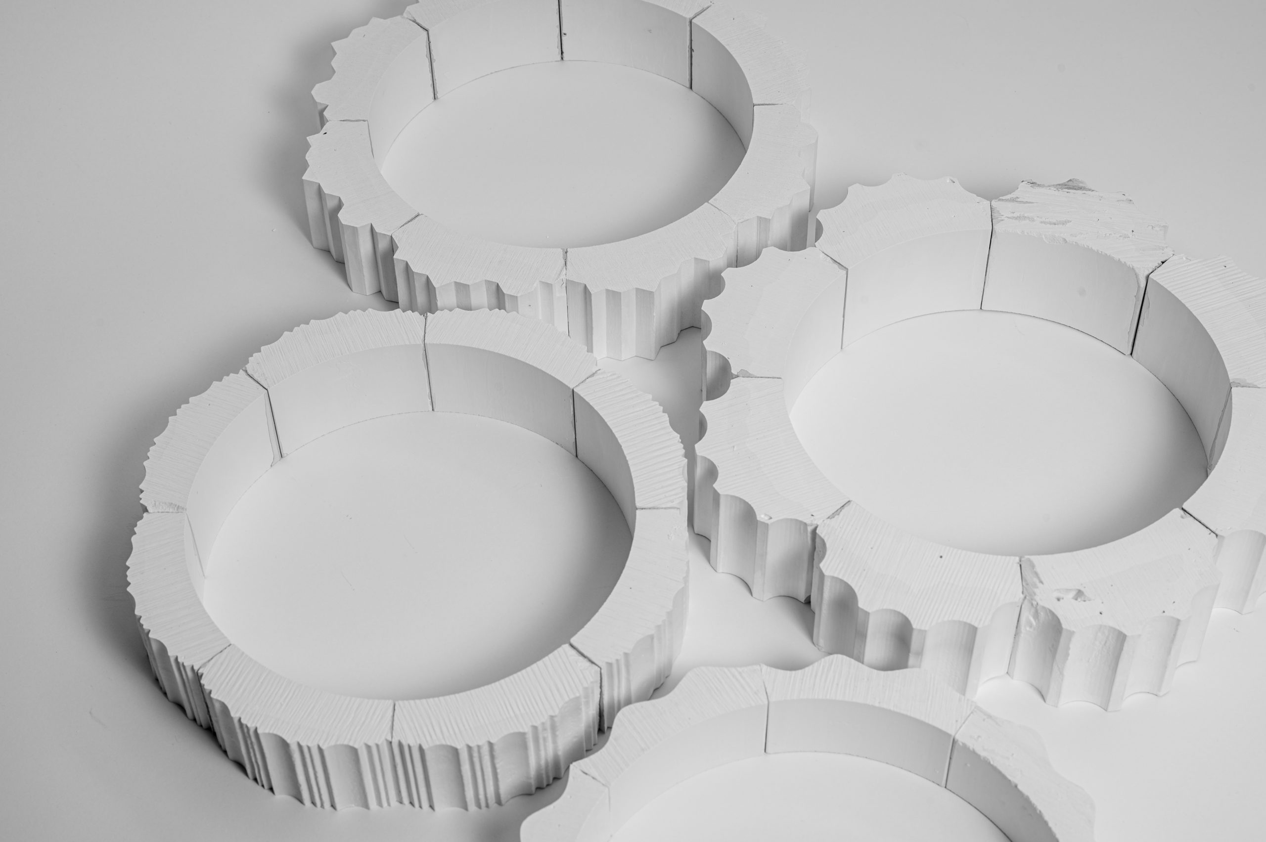
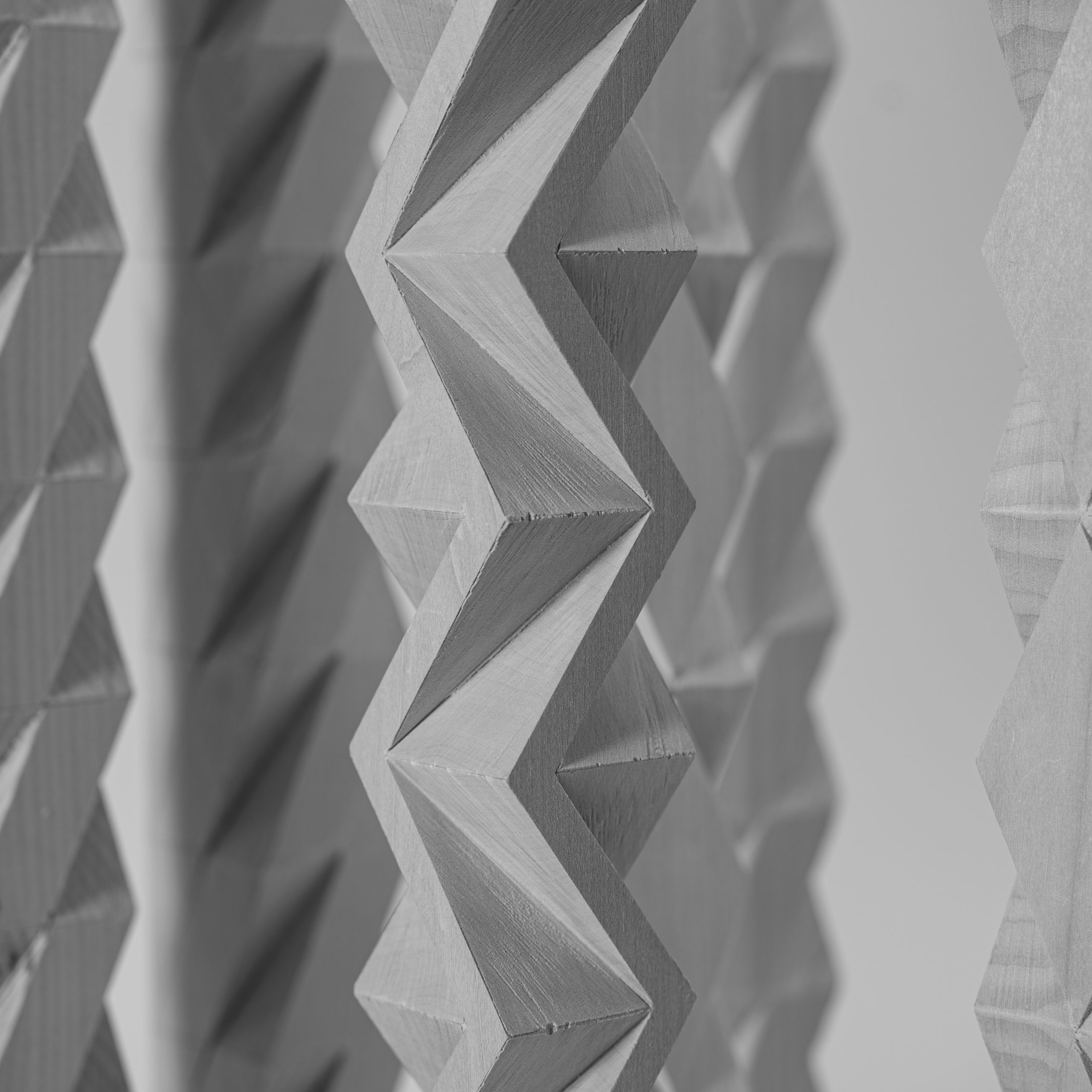
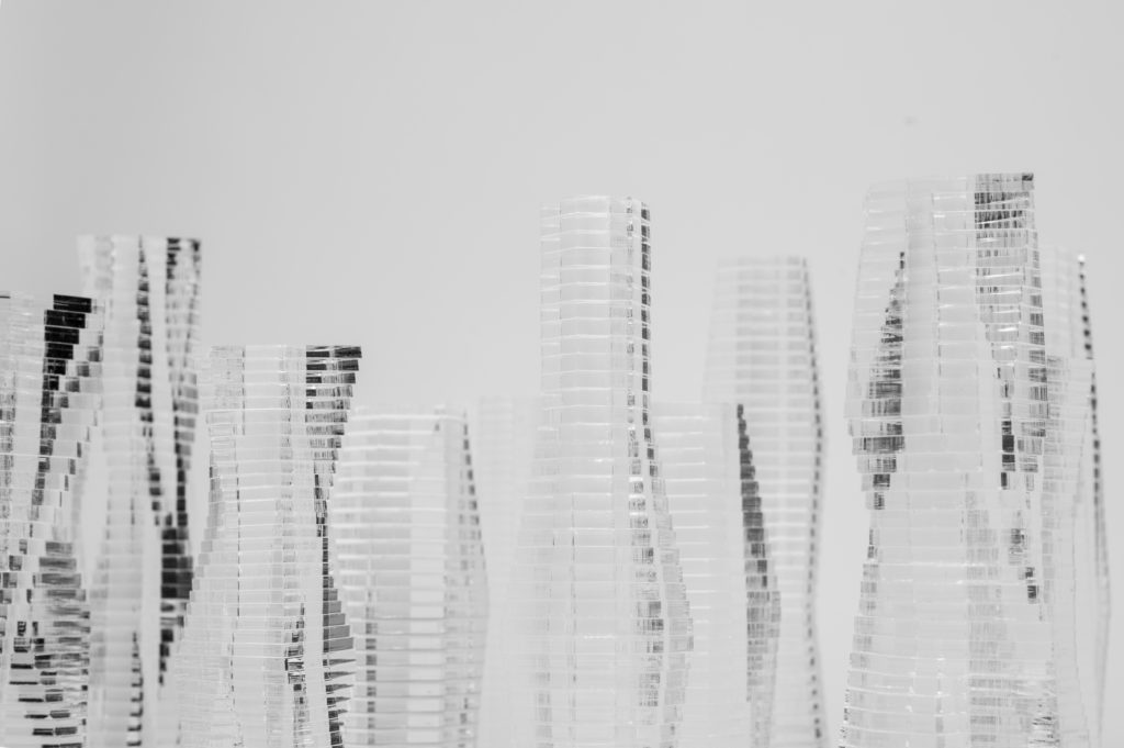
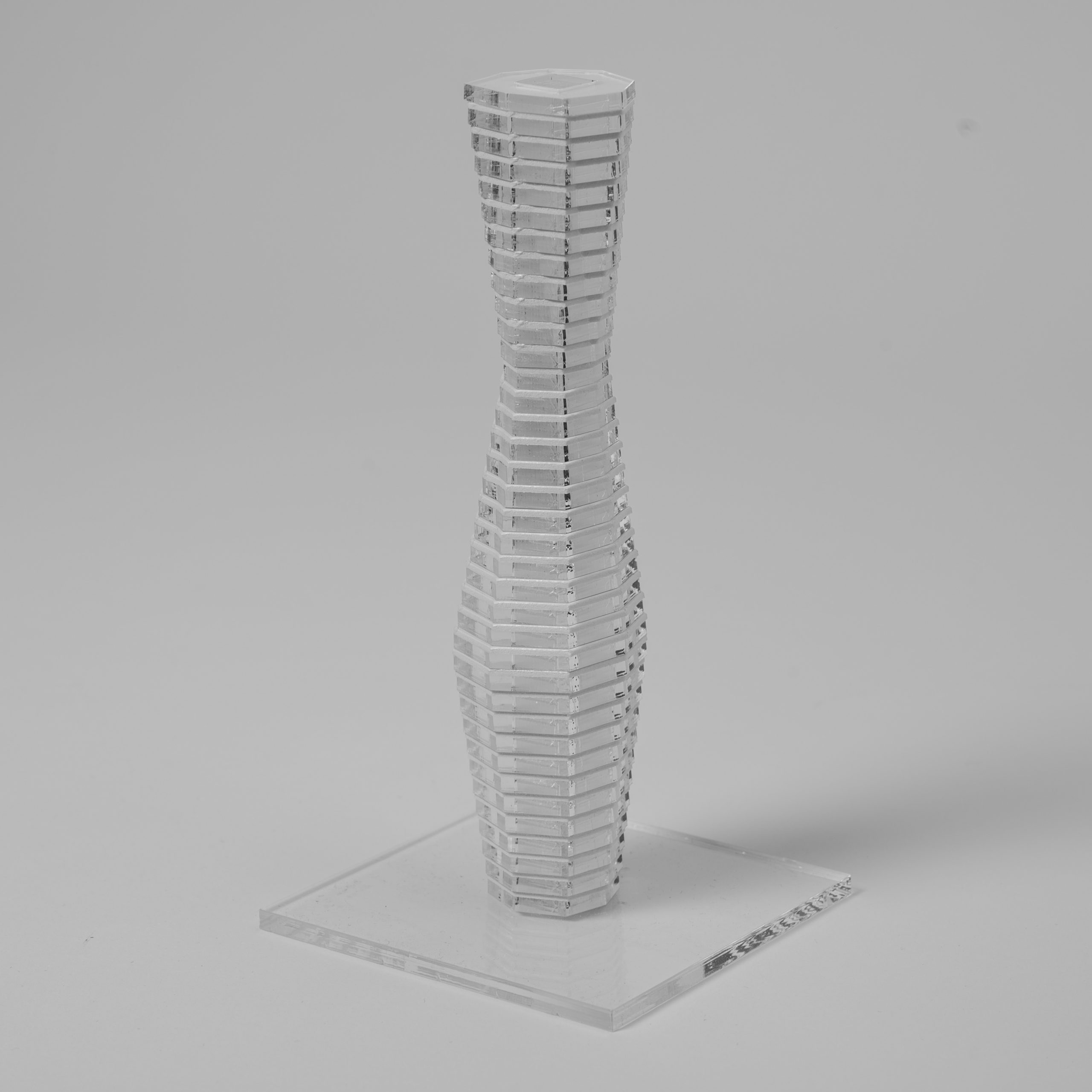
For this tutorial, a simple profile was chosen as the basis for creating a plaster extrusion that gets assembled into a ring of eight segments.
Having methods and techniques at hand that allow the creation of complex objects is of great importance in model building. It allows the designer to think in different materials and lets him or her express form in a more precise way.
Keep in mind that you will benefit the most from working with this material if you apply your twists and variations to it and do not just follow the examples.
Plaster Jack
Design Rules
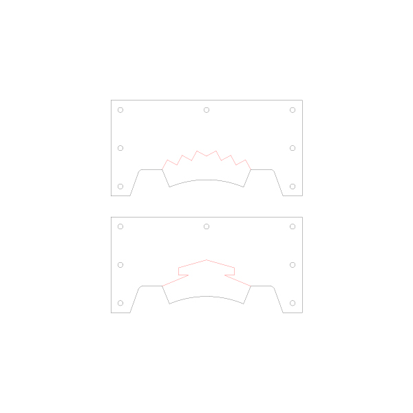
Base Template
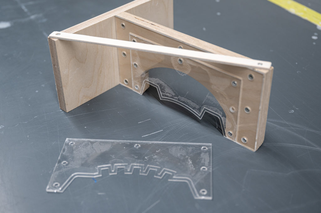
Profile Template
Extrusion
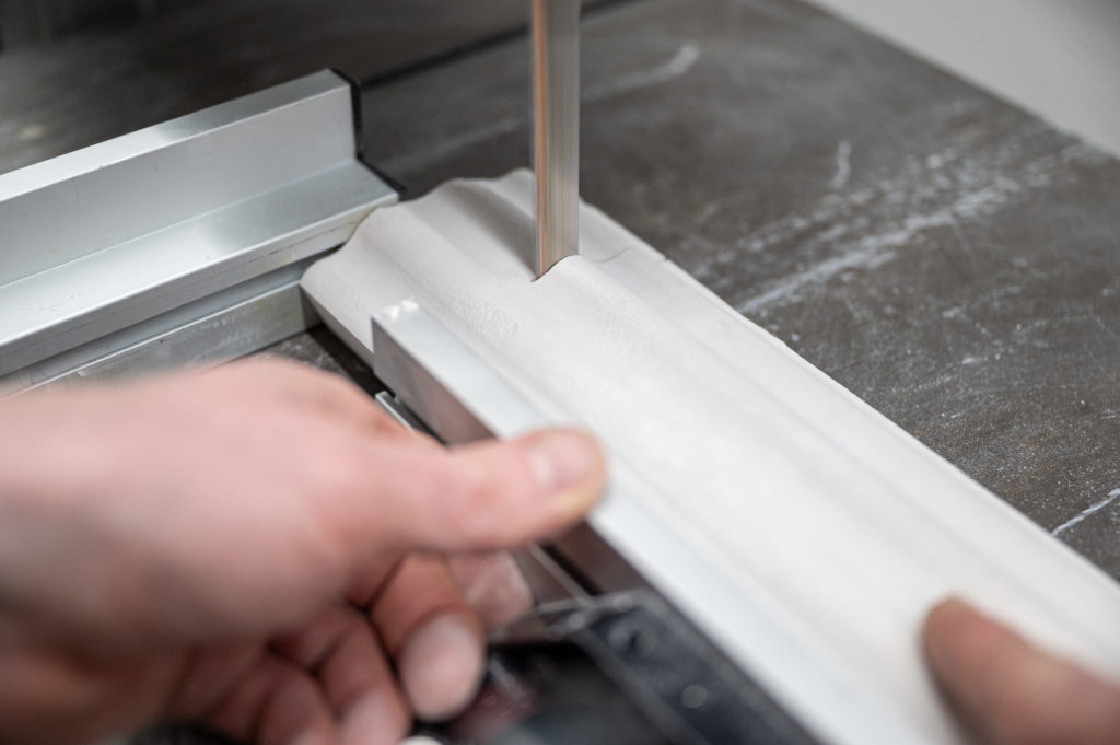
Assembly
Material
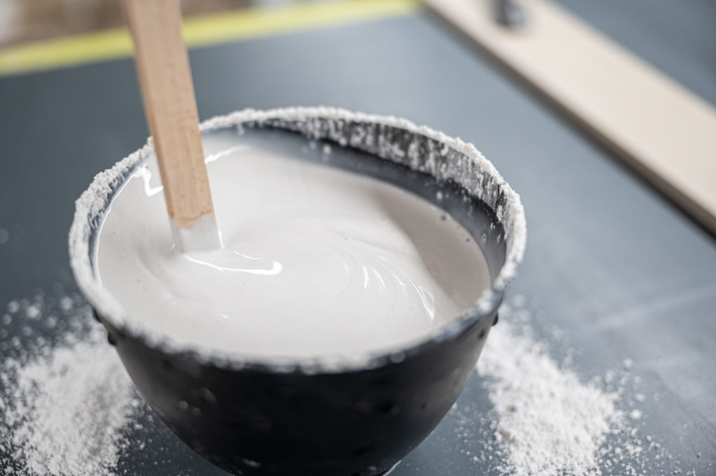
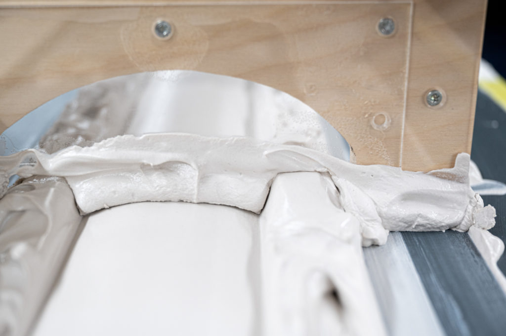
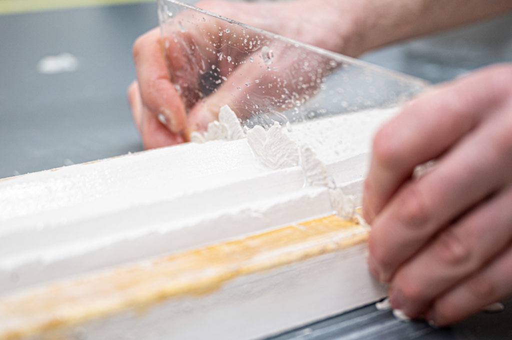
Plaster, properly understood, can be used in different stages of its hardening process. The most common way of working with plaster is, of course, pouring, but carving, sculpting, extruding, and even turning is possible.
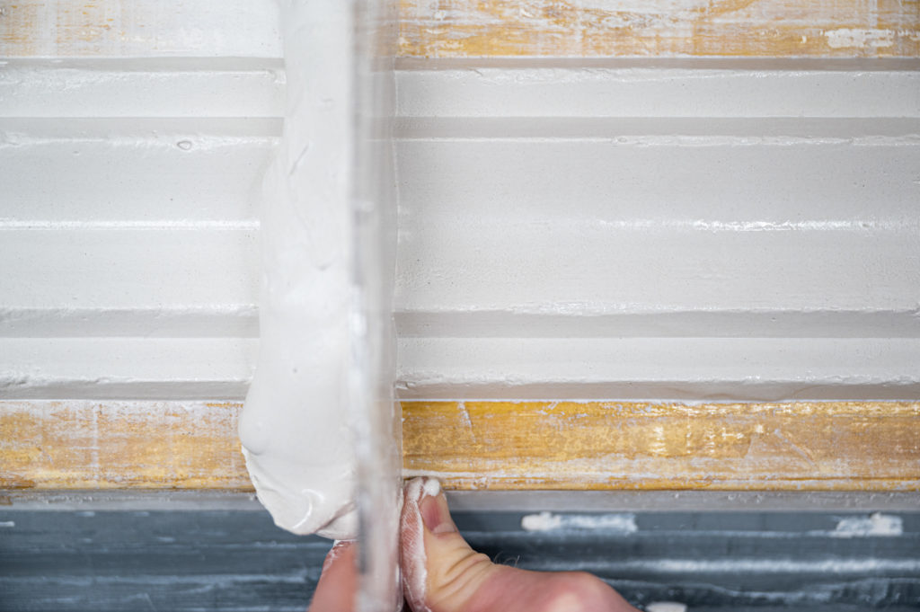
The extrusion process takes advantage of the fact that plaster has a gentle curing curve. Freshly mixed, it is too liquid to be of use for extruding the material, and a bit of patience is needed to get to the right consistency where the plaster is almost like cream cheese. In this phase, plaster builds up quickly and can be extruded into nearly any shape.
Scale: 1:200 Material: MDF, Paint, Paper and others
The Basic Design
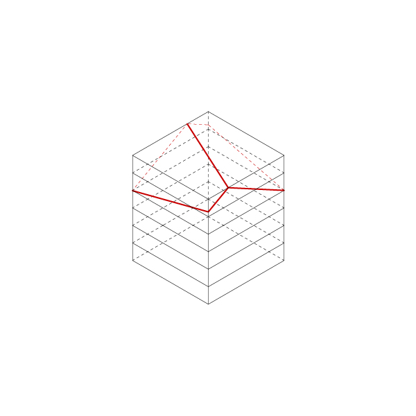
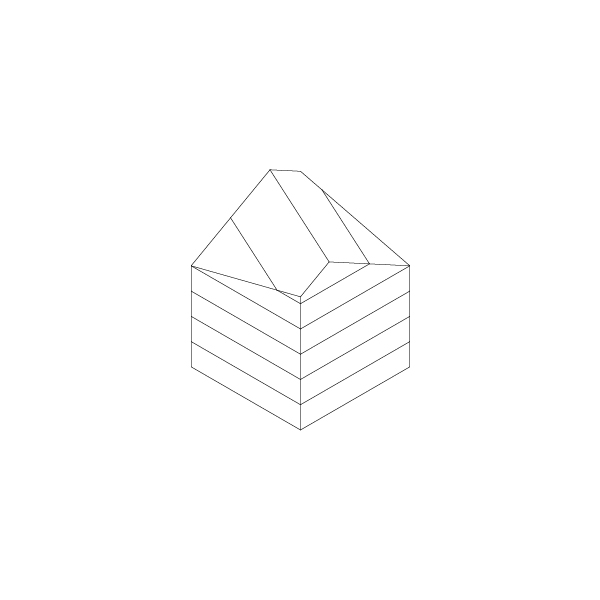
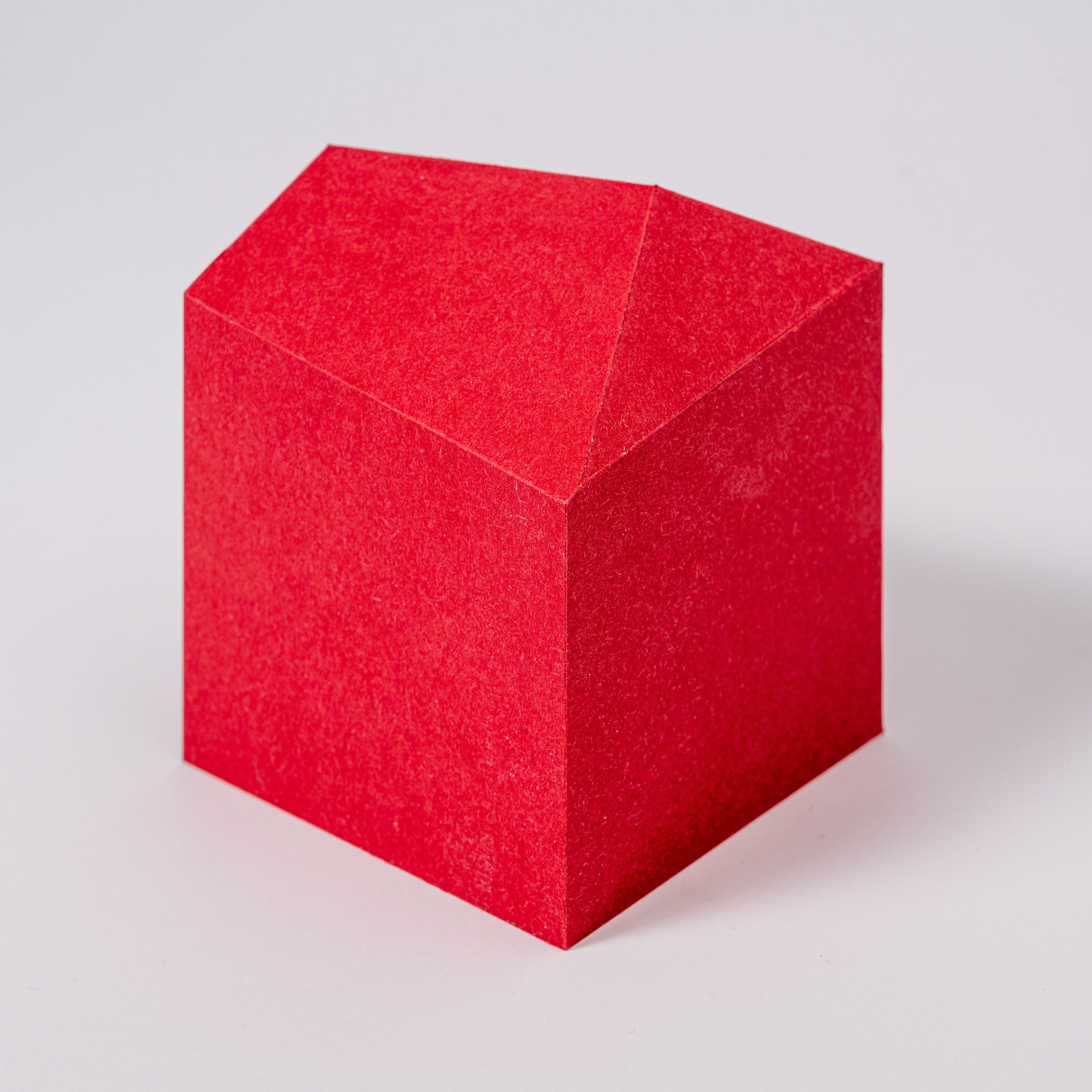
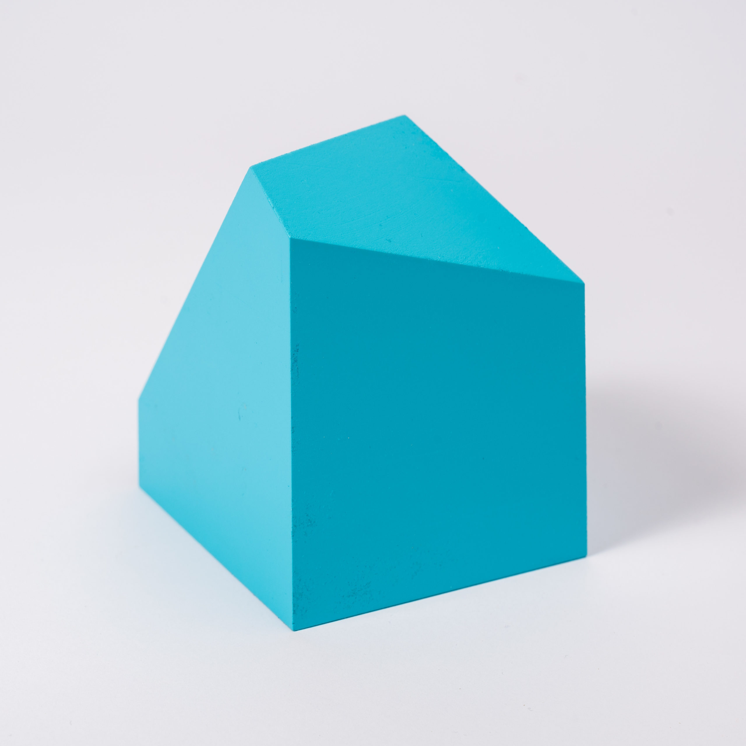
For this tutorial, we’ve chosen a simple house shape based on a familiar archetype of the pitched roof with a slight variation to add a bit of interest. Feel free to experiment and make up your criteria for finding exciting shapes and solutions, or try the techniques demonstrated in this post on one of your designs to work in a more realistic setting.
Keep in mind that you will benefit the most from working with this material if you apply your twists and variations to it and do not just follow our examples.
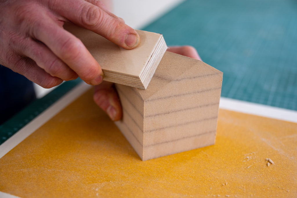
MDF Block
Roof Ridge
Gabel Roof
Volume
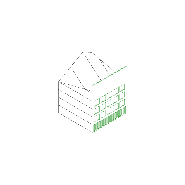
Facade
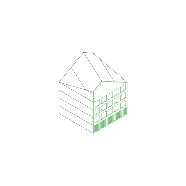
House
Material Choice
There are two routes to choose from. In this application, professional model builders would work with a dense polyurethane block material (Renshape, Ureol, Sika Block, Obomodulan). These materials have several advantages like they’re fast to work with, have no internal stress, and can be painted with several finishes. On the other hand, these highly specialized models are too expensive to use during the design process.
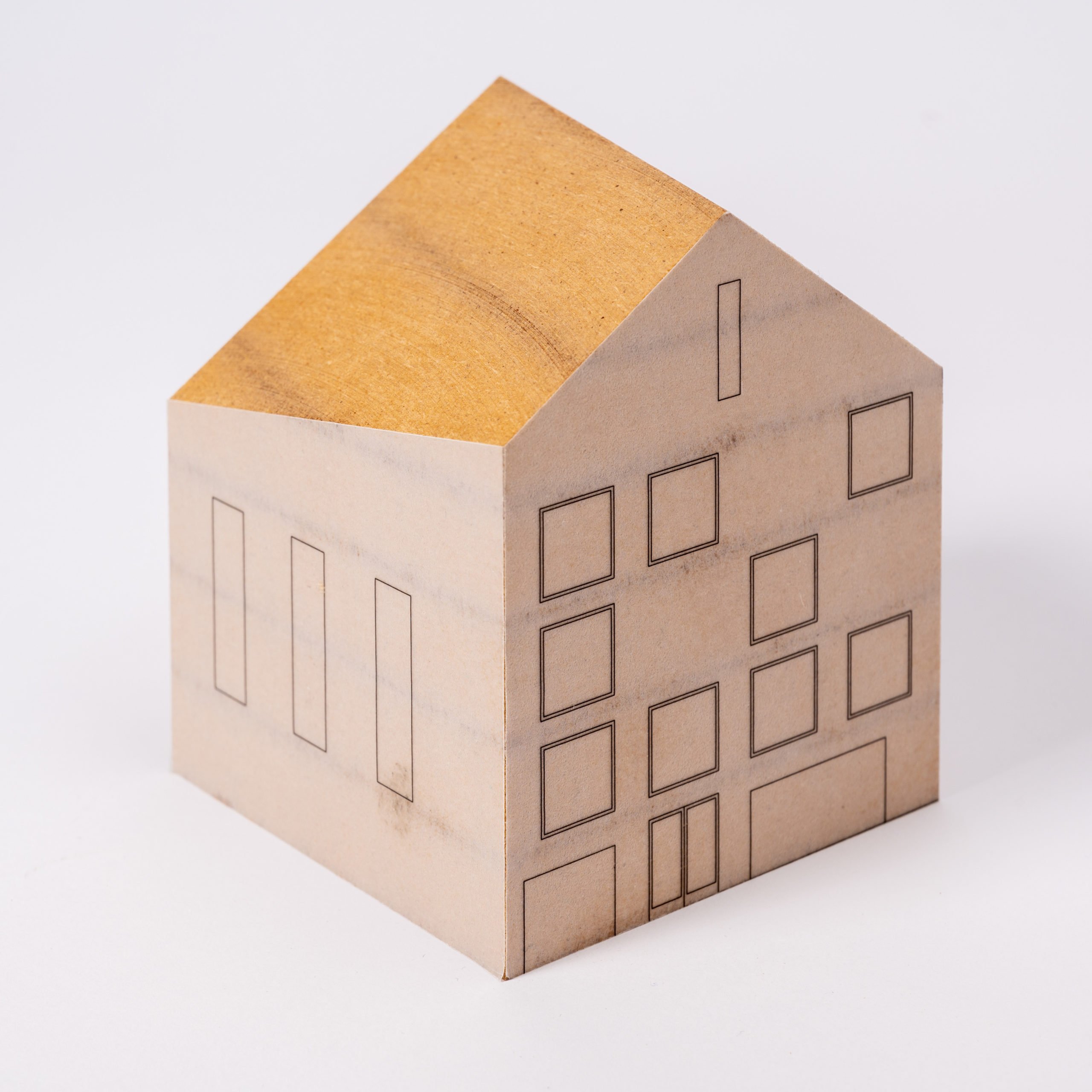
MDF (Medium Density Fiberboard) is readily available in most parts of the world and can even be picked up as scraps from carpenters for model building purposes. On the scale of 1:200, a 16mm MDF plate relates to a typical floor height (~3.2m), and on the scale of 1:500, a 6mm MDF does the same (~3m). The relationship between material thickness and floor height allows us to incorporate the natural divisions of a glued-up block into our models.
Techniques For Working With MDF
Gluing
MDF is best glued with white glue or medium viscosity super glue.
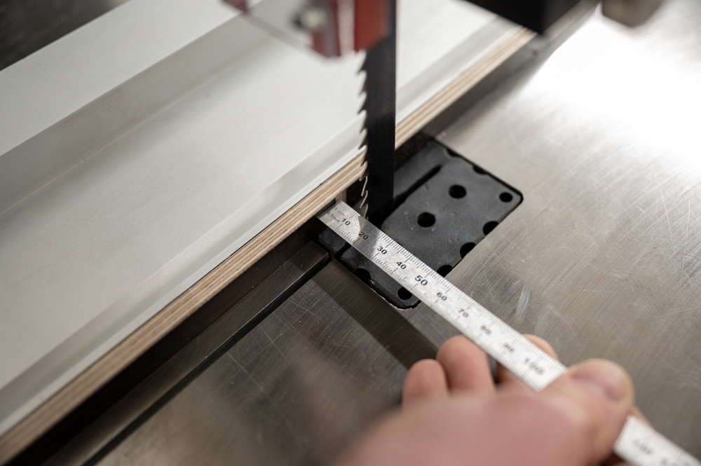
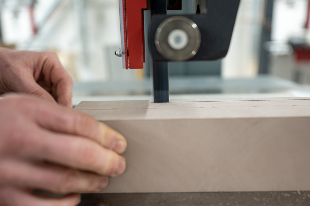
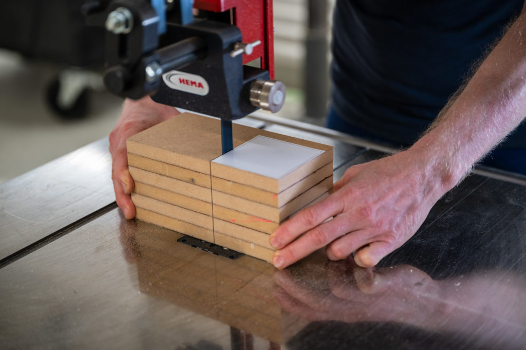
Cutting
MDF blocks can be cut to rough dimensions with the bandsaw.
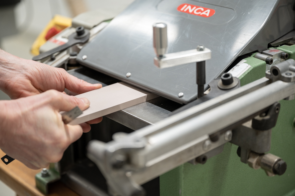
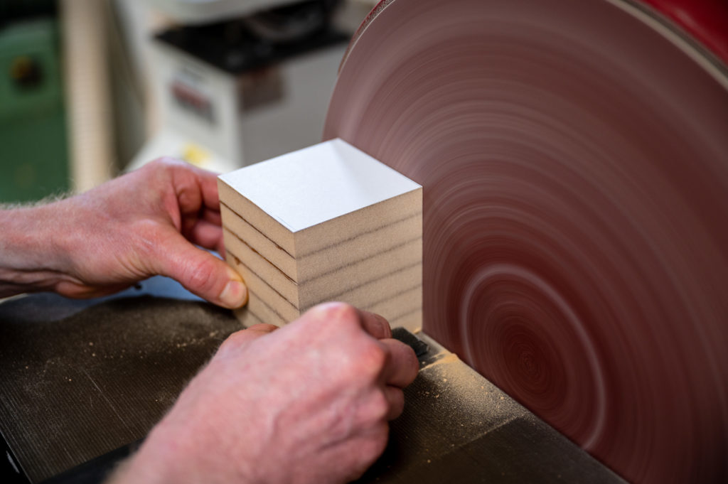
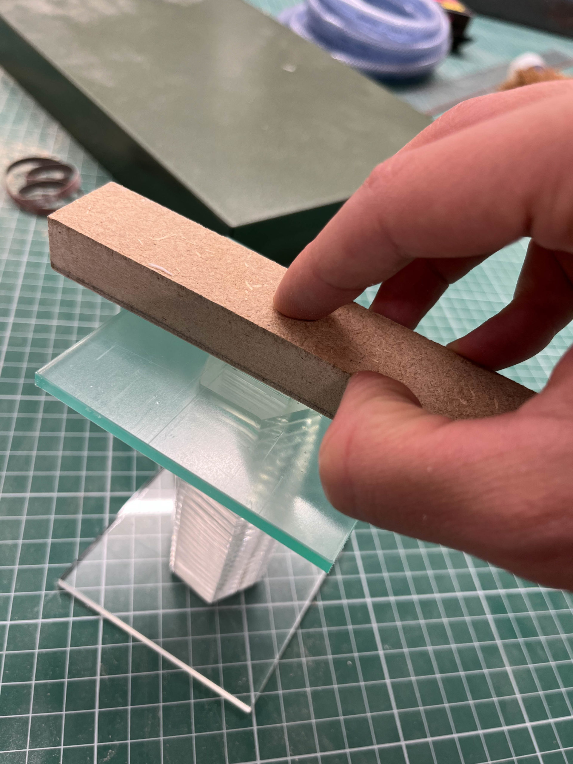
Template Sanding
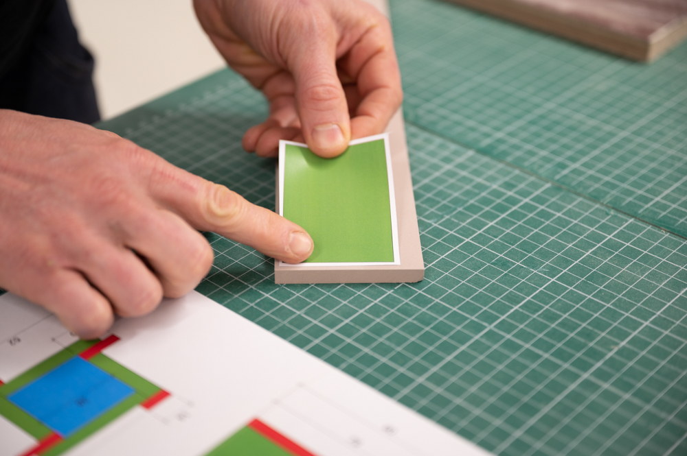
MDF can be shaped on the disc sander to precise dimensions with the help of a printed layout that is applied with removable spray adhesive.
Final Sanding
Is best done by hand with 220 grit sandpaper mounted to a flat surface or with a self made sanding block.
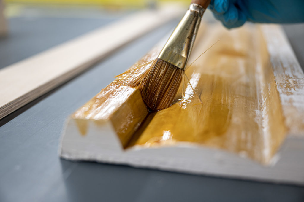
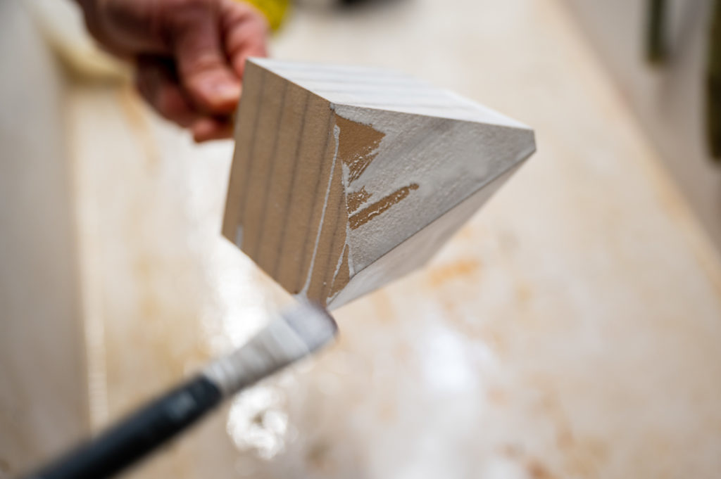
Tinting
Applying emulsion paint thinned down with water with a soft brush results in a seethrough finish. This technique is ideal for buildings that are relevant to the context of your design.
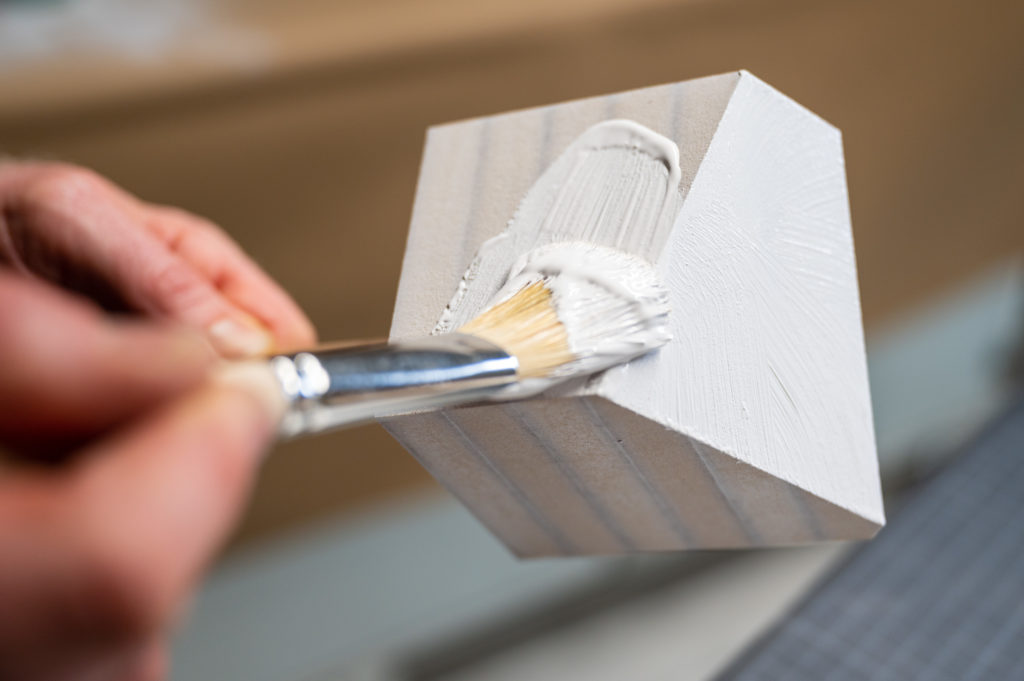
Filler
Brush on a thick layer of emulsion paint as filler for MDF. After drying, the block is sanded with 220 grit sandpaper and ready for spray painting. Repeat the process if the block still feels porous after sanding
Painting
After sanding the filler, you can apply any acrylic spray paint to color your volume.
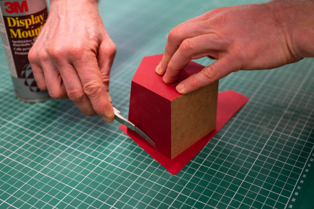
Paper Laminate
For a discrete mat finish paper can be glued to the volume by applying spray adhesive.
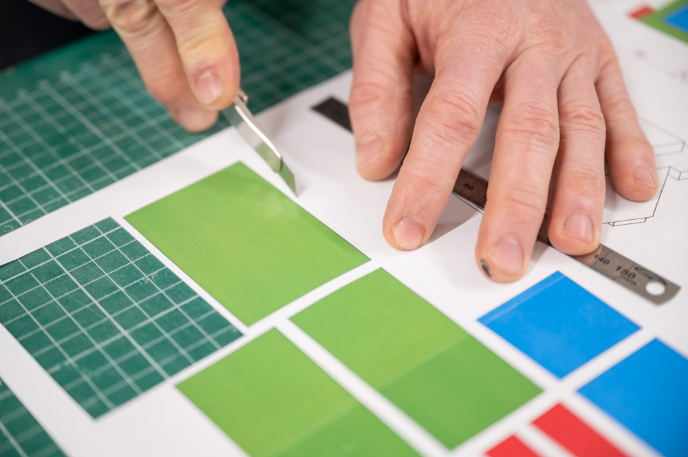
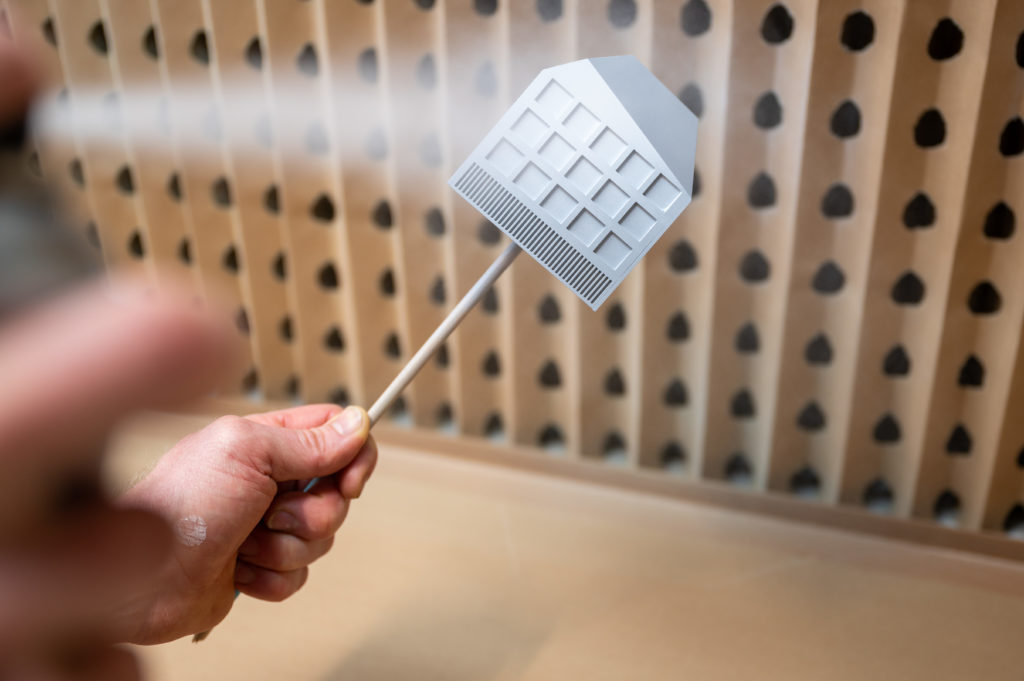
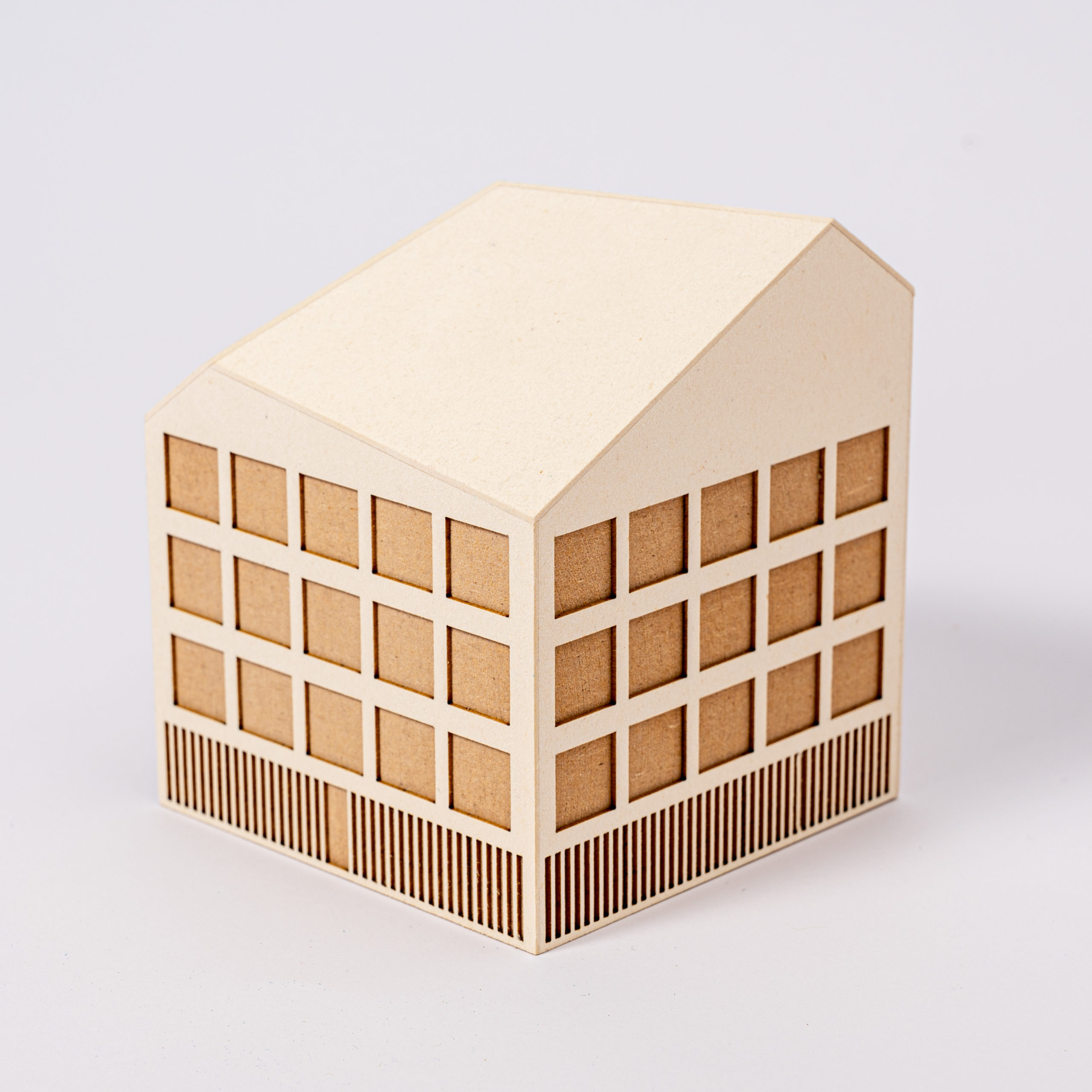
Facade
A simple way of adding detail to the block is to glue a laser-cut acrylic or card facade to the volume. This technique requires additional sanding and finishing and shows the method’s potential for designing with models – the model transforms as the project evolves.
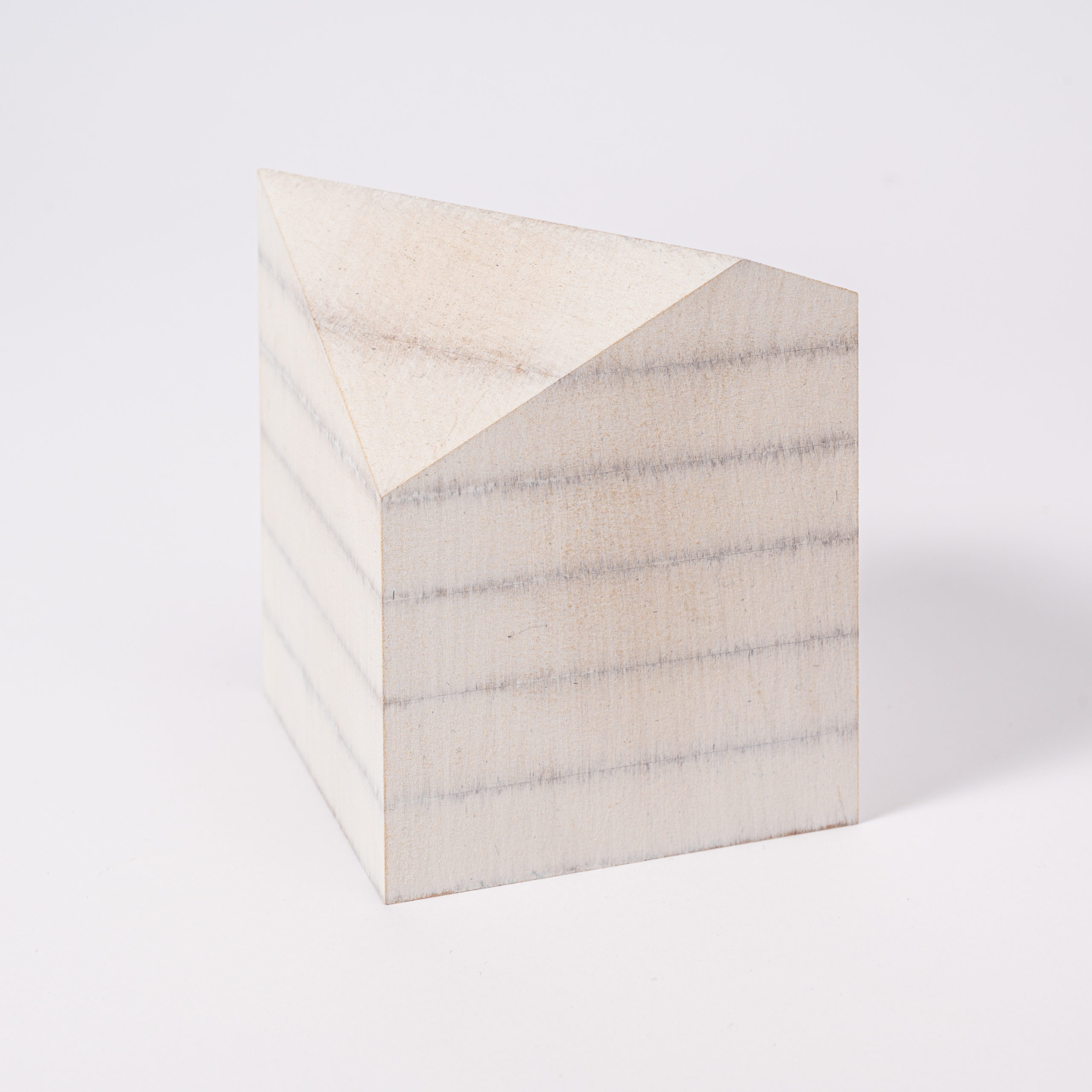
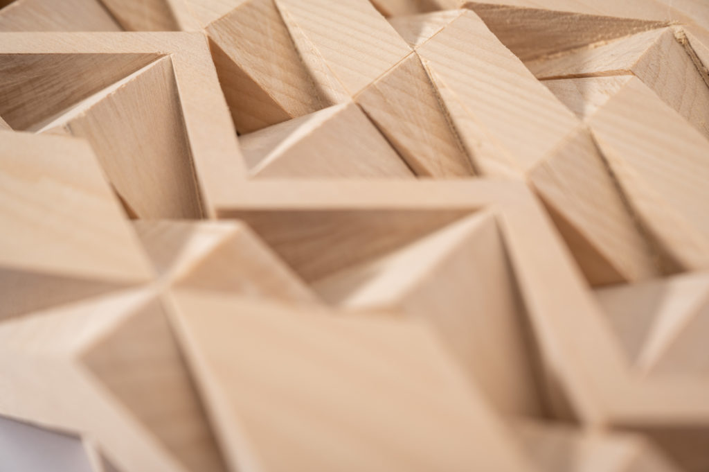
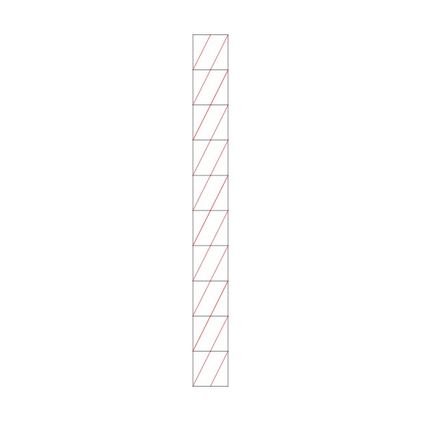
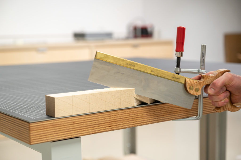
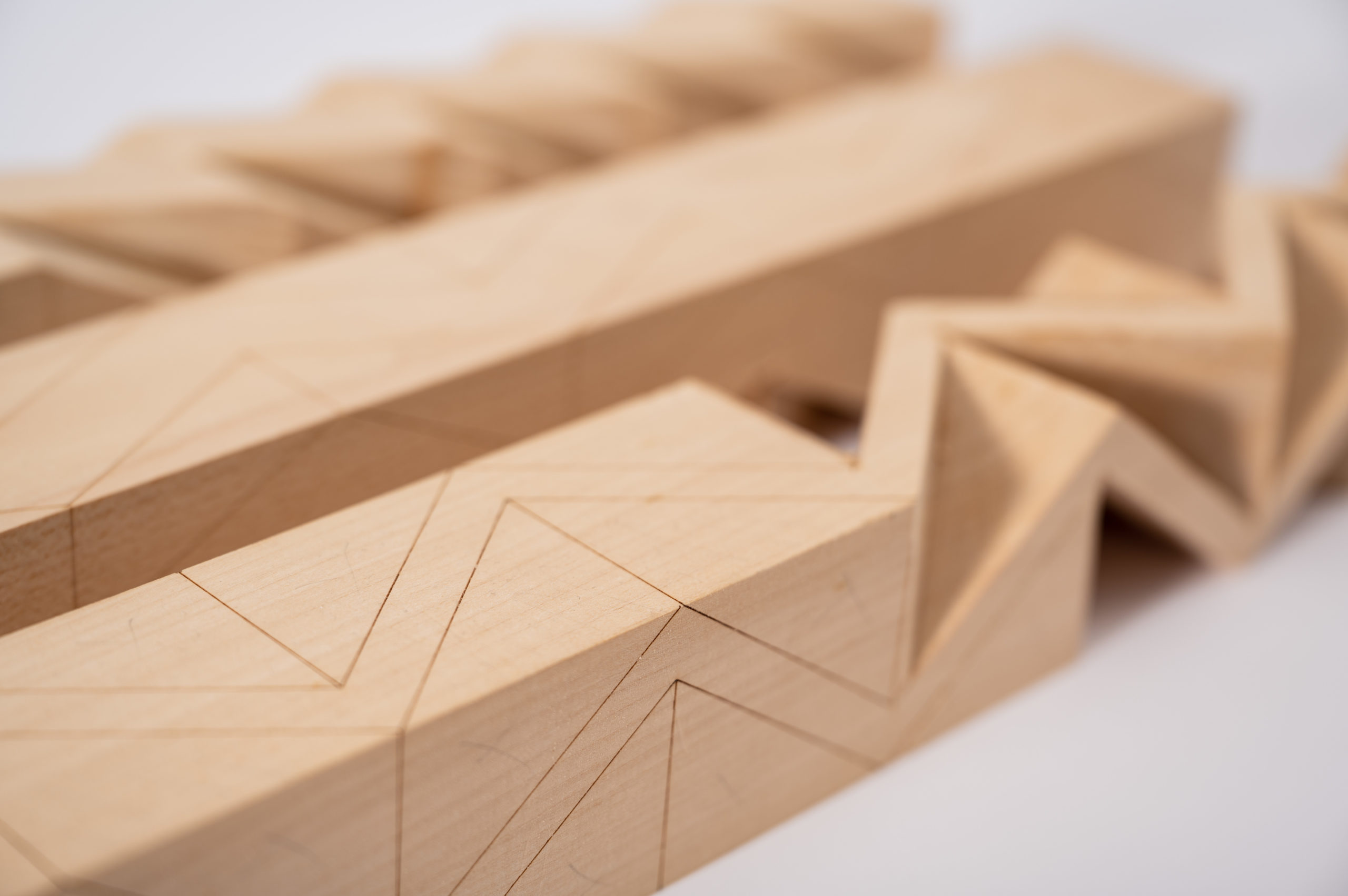
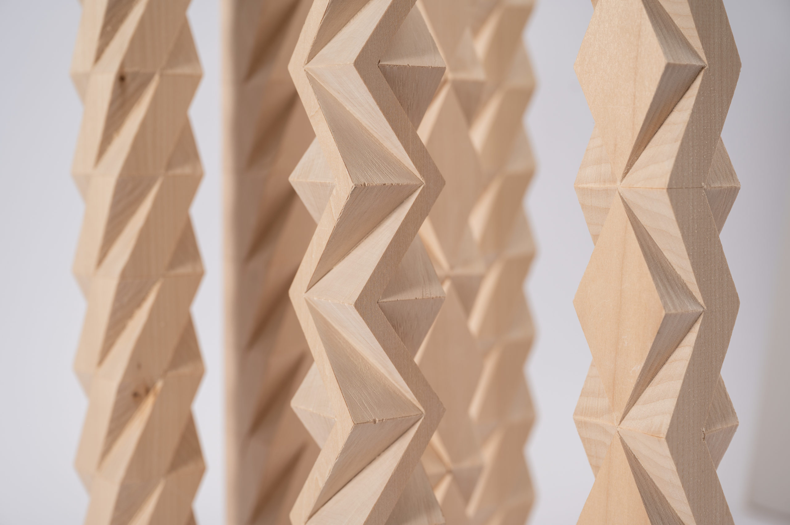
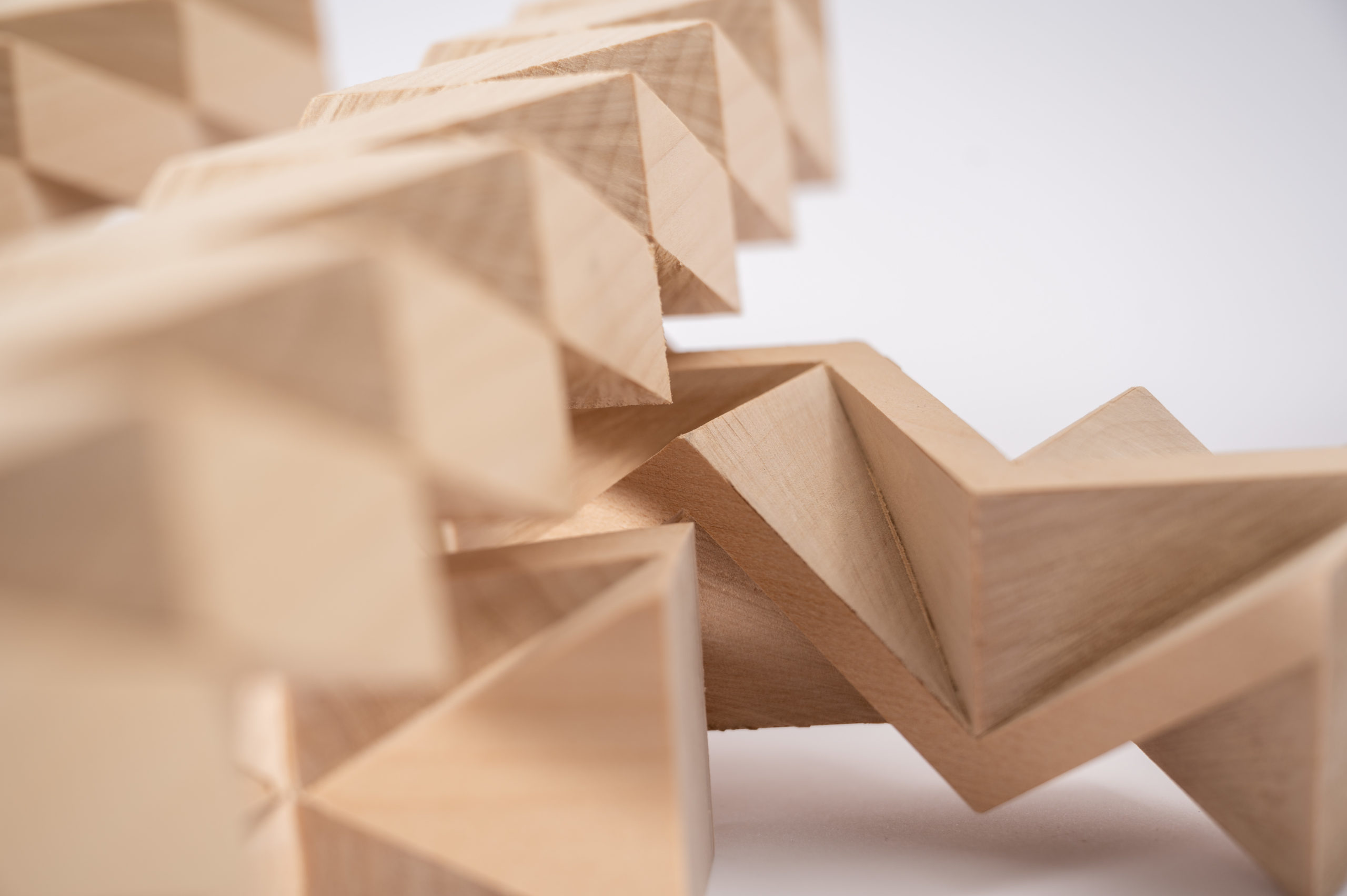
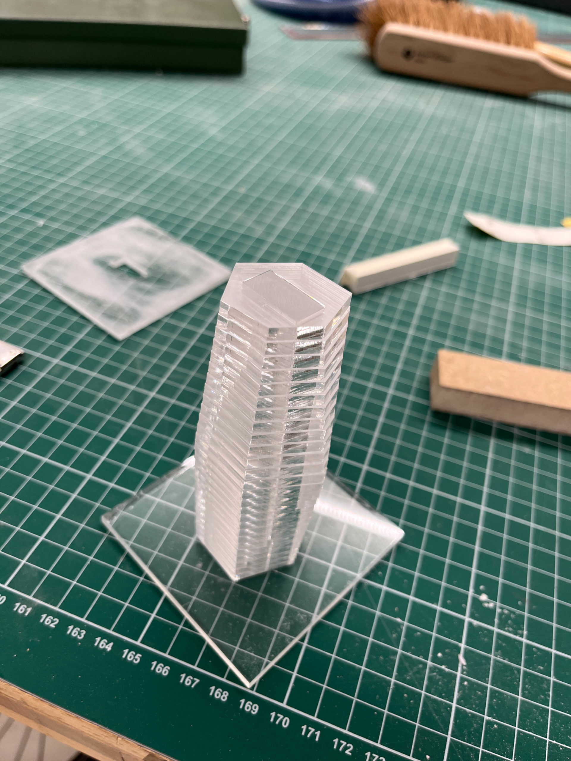
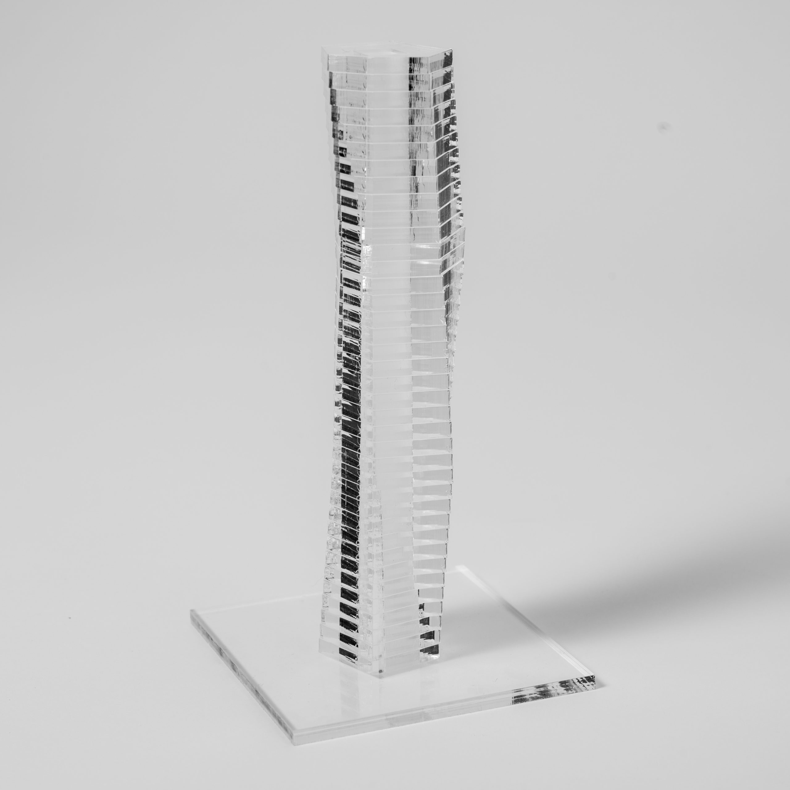
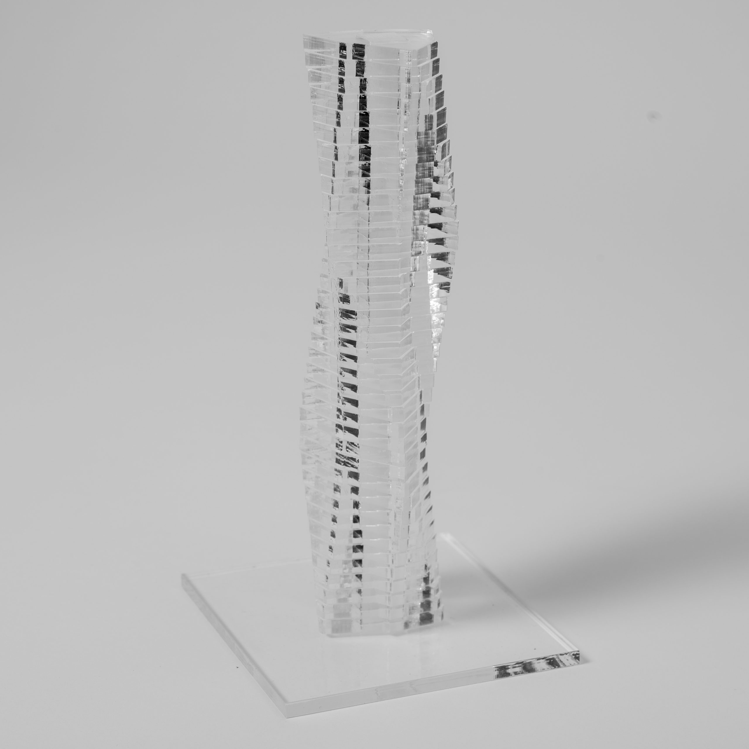
Using a handsaw is a liberating experience. Once mastered, the saw allows for intricate cuts with very high precision. Other tools would require complex jigs and work holding devices to achieve similar results.
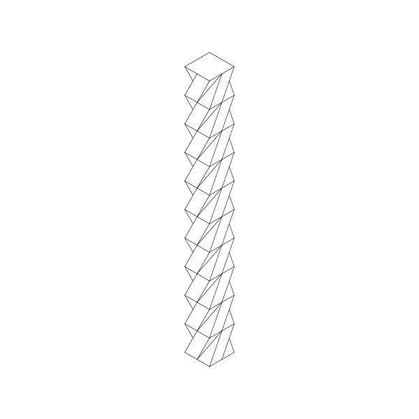
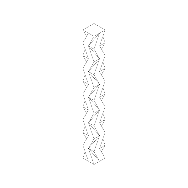
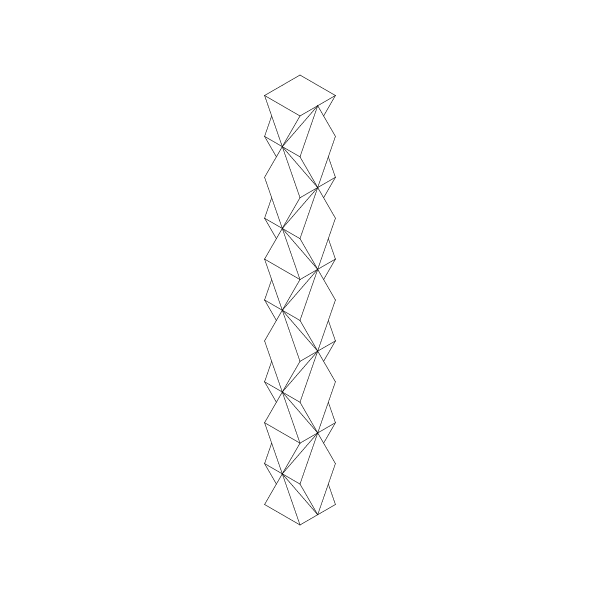
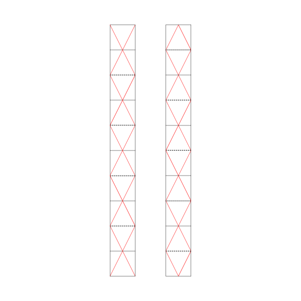
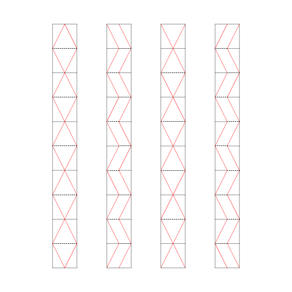
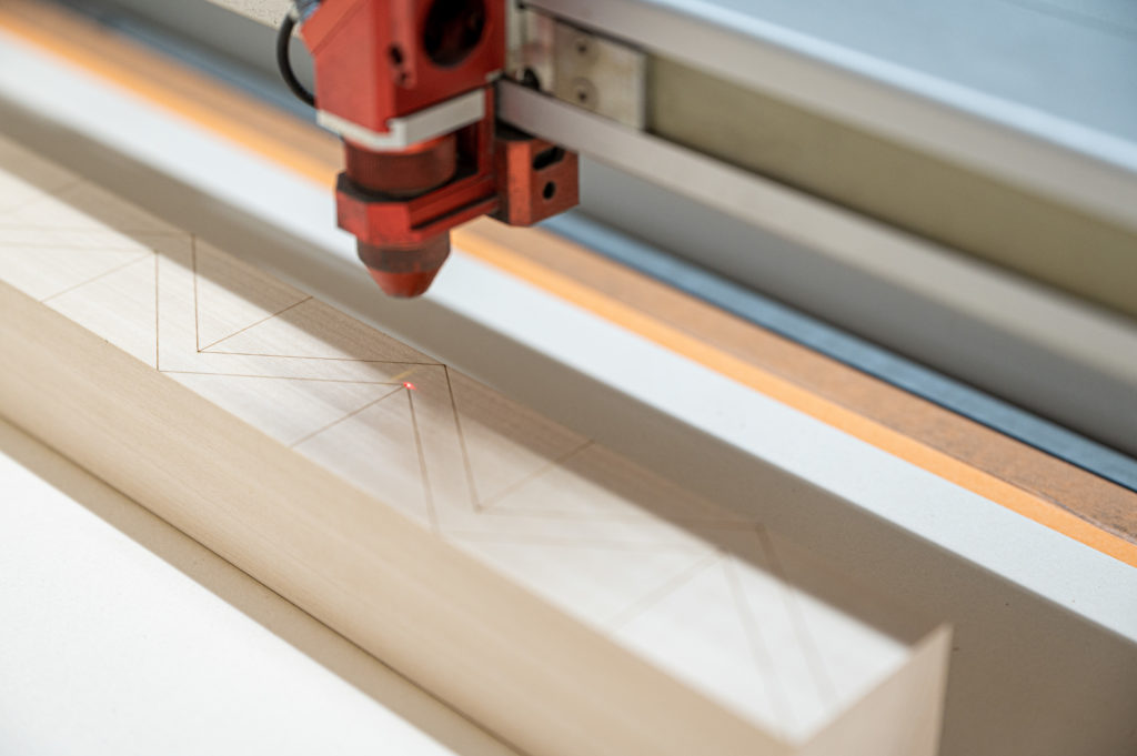
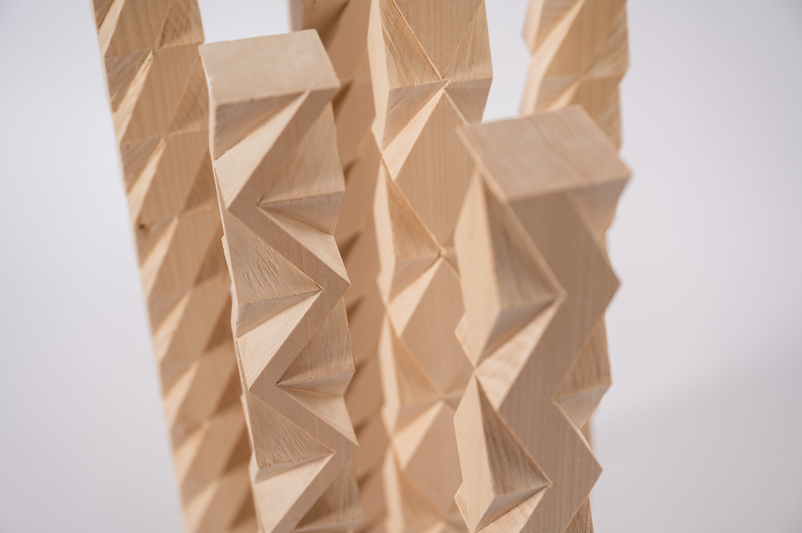
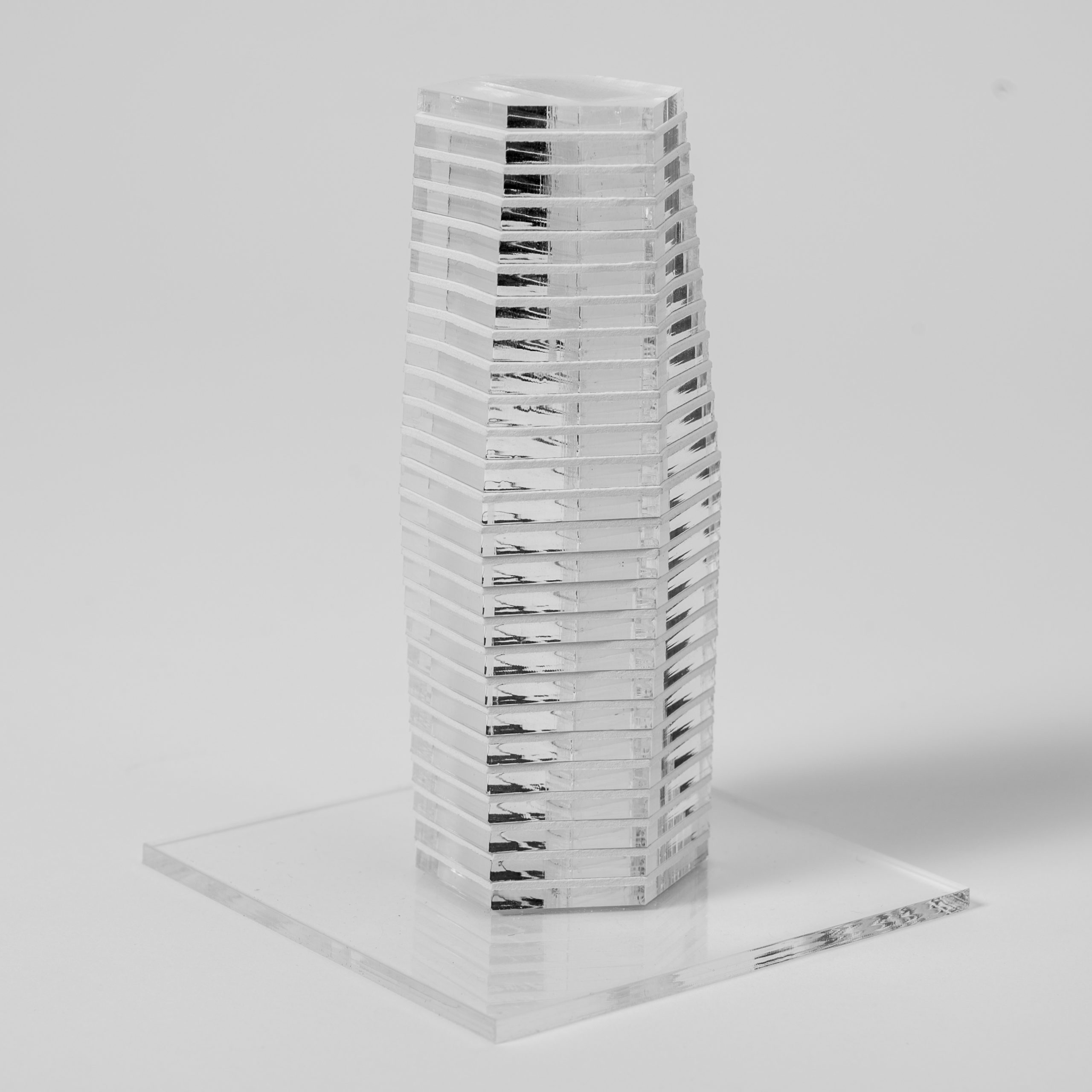
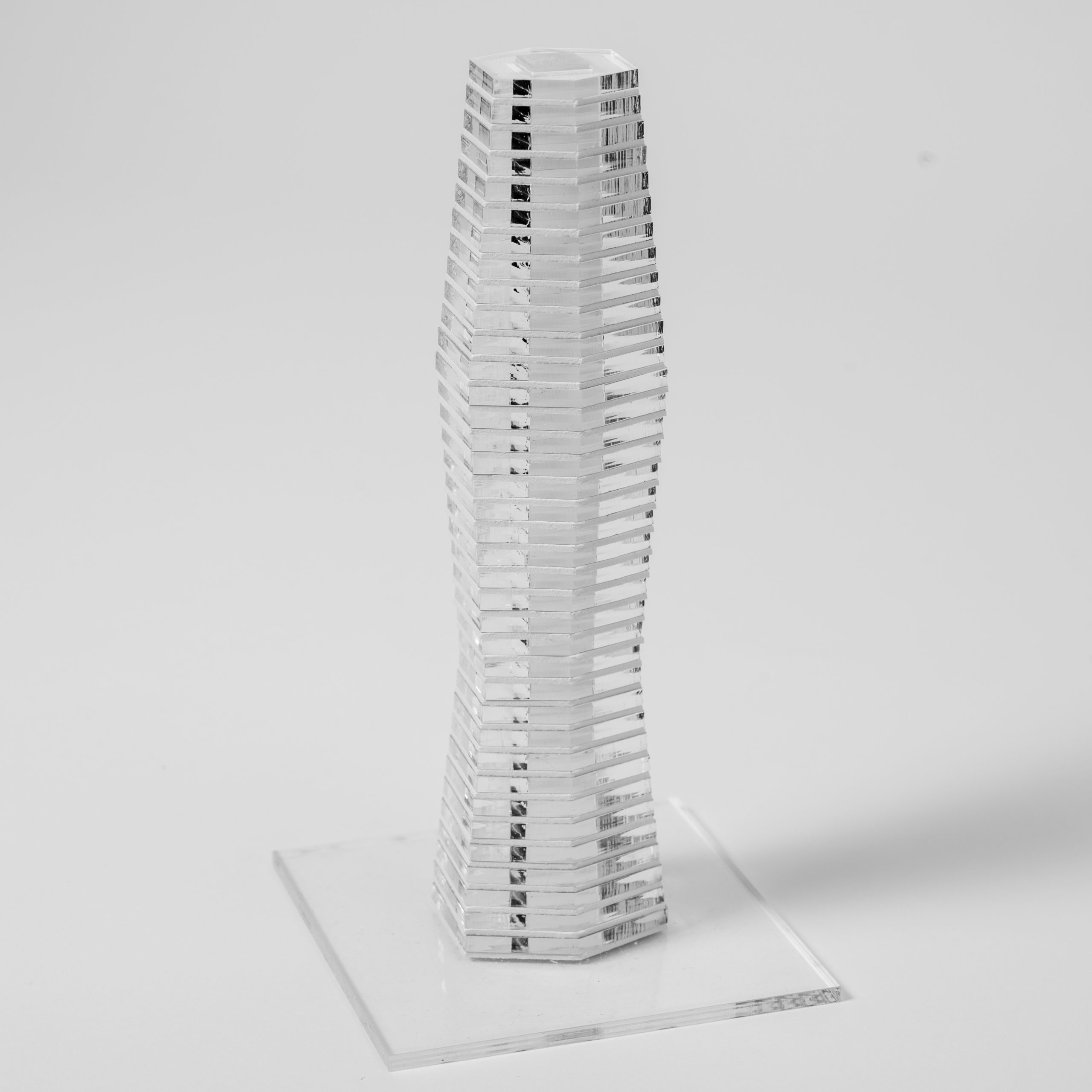
Following this freedom of cutting at any angle, we chose simple cubes as a starting point. The incisions are based on simple geometric constraints, like diagonals and mid-points. Repeating the pattern results in a longer profile marked with the help of a laser-cutter. The exercise tries to combine the advantages of analog and digital work so that both approaches work together to achieve the final result.
Supplemental material on cube subdivisions and the original material in terms of geometry can be found in the book: Papier, Versuche zwichen Geometrie und Spiel by Franz Zeier
Keep in mind that you will benefit the most from working with this material if you apply your twists and variations to it and do not just follow the examples.
Column A
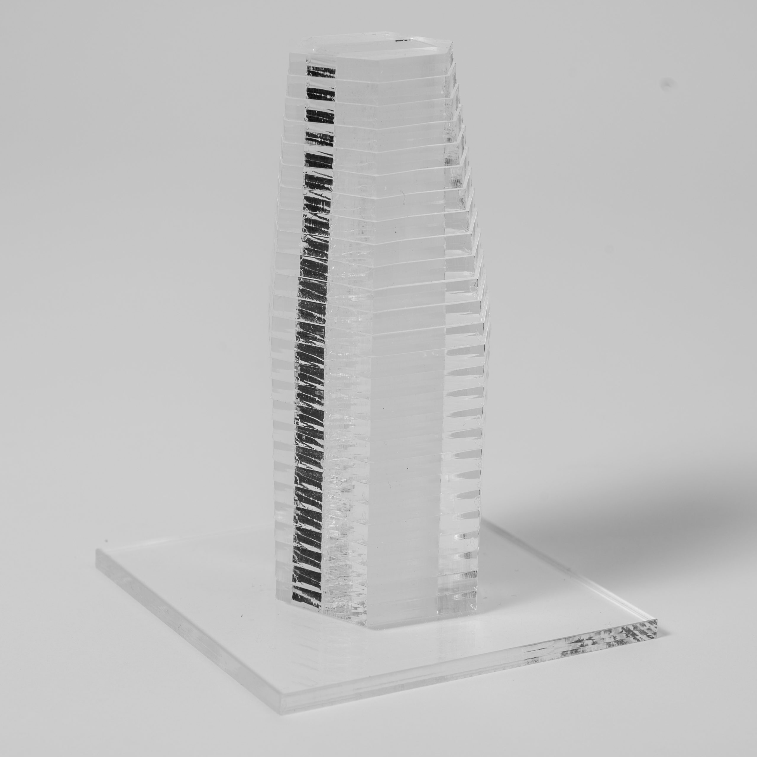
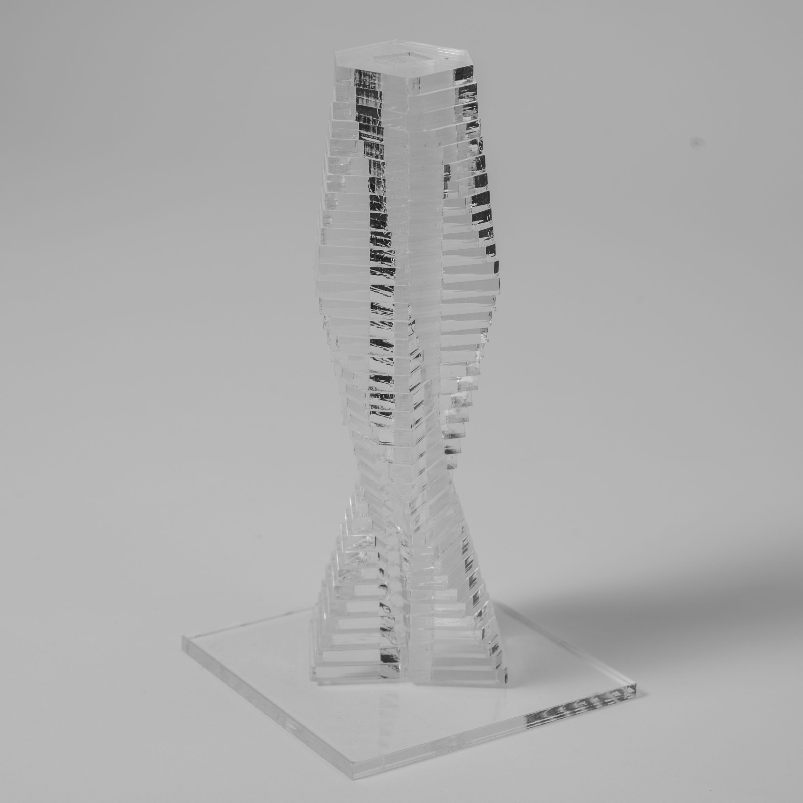
Column B
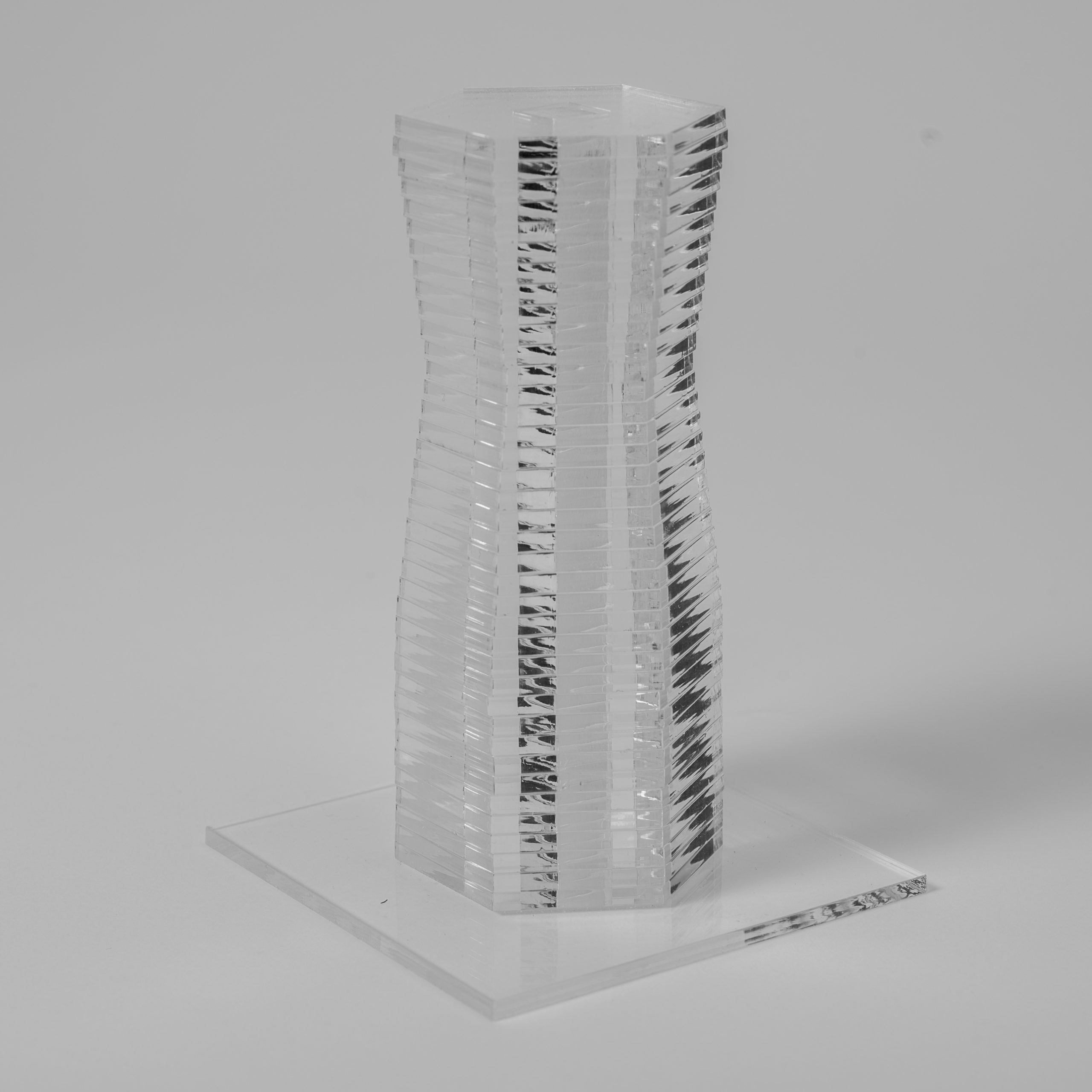
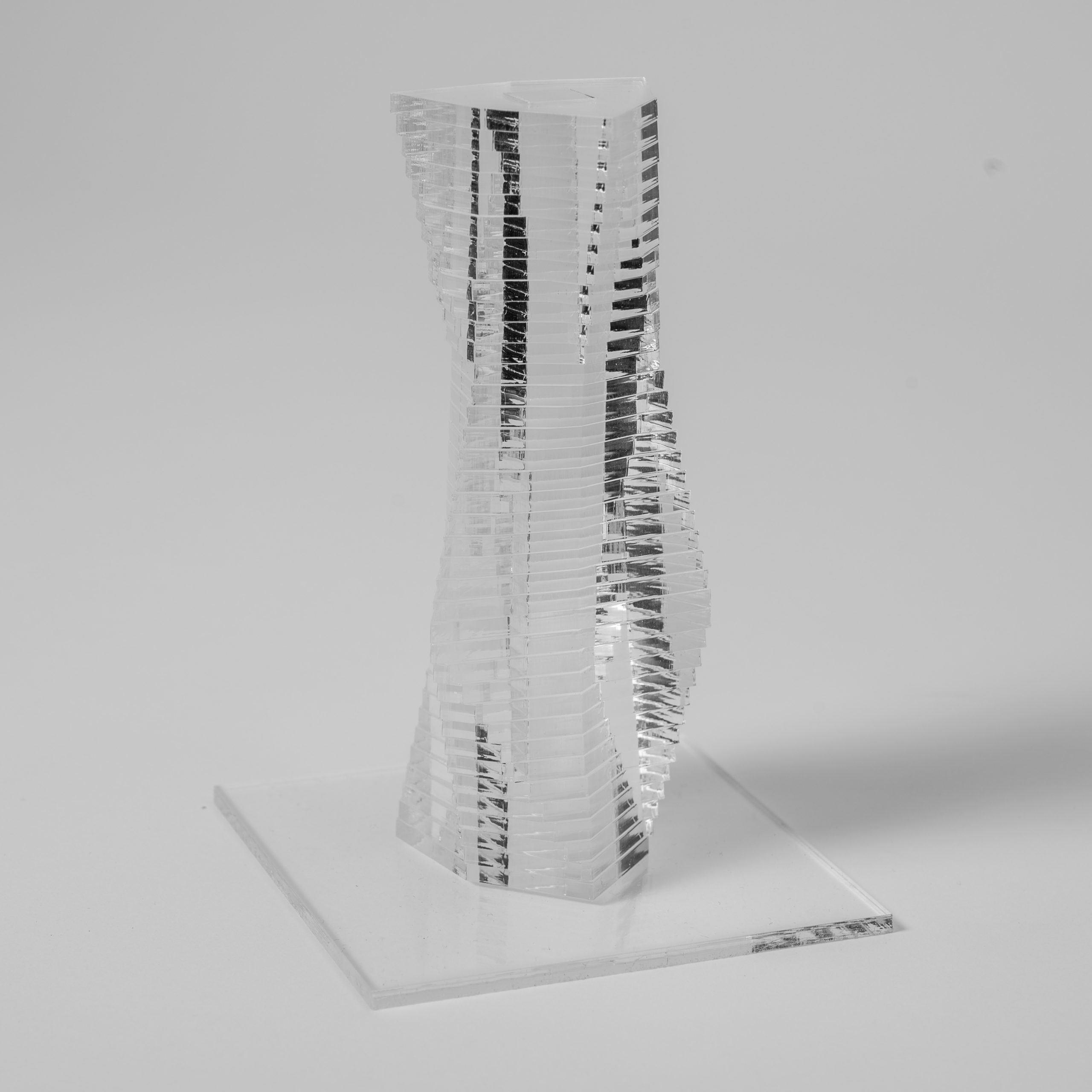
Column C
Column D
Cutting Pattern A
Cutting Pattern B
Cutting Pattern C
Cutting Pattern D
Material
Basswood is frequently used for model building due to its great workability. It can be worked with machine or hand tools equally well and comes in a reasonable variety of dimensions, some of them already planed to size, others rough and more suited for larger work. Model builders like basswood because of its gentile and none dominate grain, a feature that allows for intricate details to be displayed without distraction by decorative grain that you often see in other species of wood. Further processing in the form of staining or painting is possible and the wood takes a wide variety of finishes. Generally it can be said that basswood is elastic and soft and a great material for carving, even across the grain. The trade off of its workability is the low impact resistance and low compressive strength.
It should be noted that sharp tools are a must due to the softness of the wood.
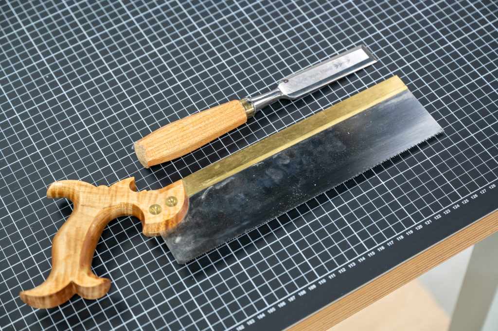
The Method
A simple handsaw and a pairing chisel are all that is needed to complete this example.
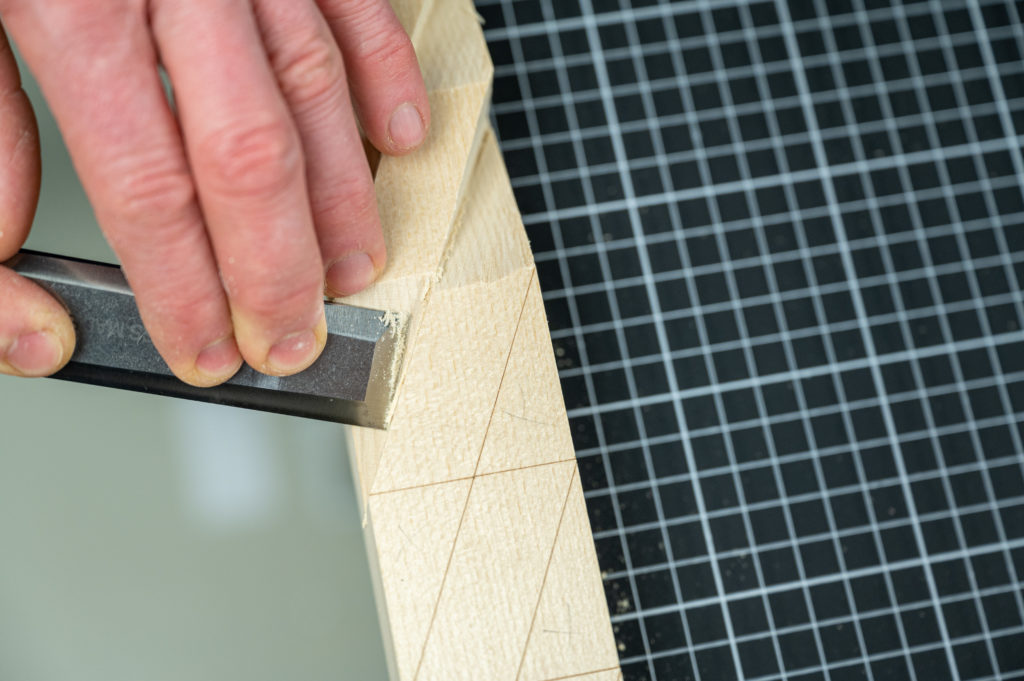
We can use the laser cutter for more than just cutting cardboard, and it is an indispensable tool for lots of other things – like marking – as well.
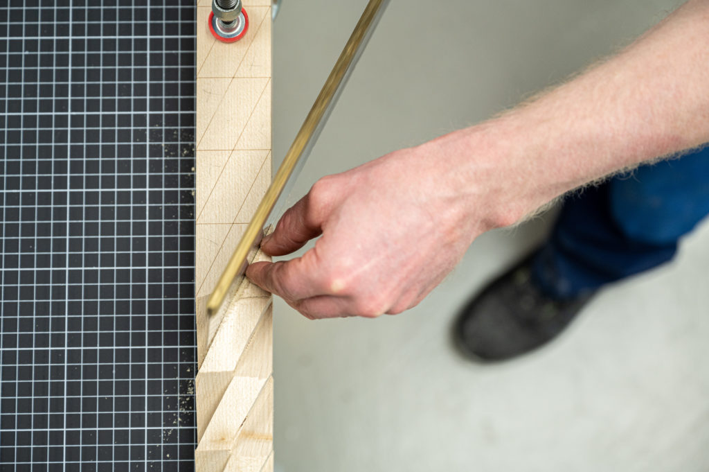
The handsaw is placed next to the cutting line to start the cut, and one hand helps guide the saw during the initial strokes.
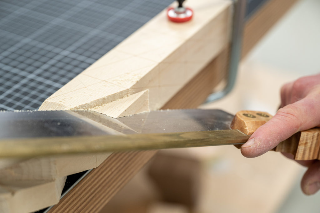
Frequently check your progress and make sure that you advance your cut on both lines.
Not ideal, but cutting weird angles and under challenging conditions becomes easier with practice.
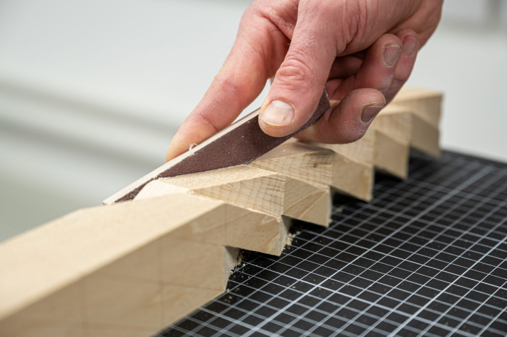
Use the lines as a guide while pairing with the chisel to your final surface.
And where would we be without our sanding blocks? A self-made sanding block helps to keep trouble spots in check.
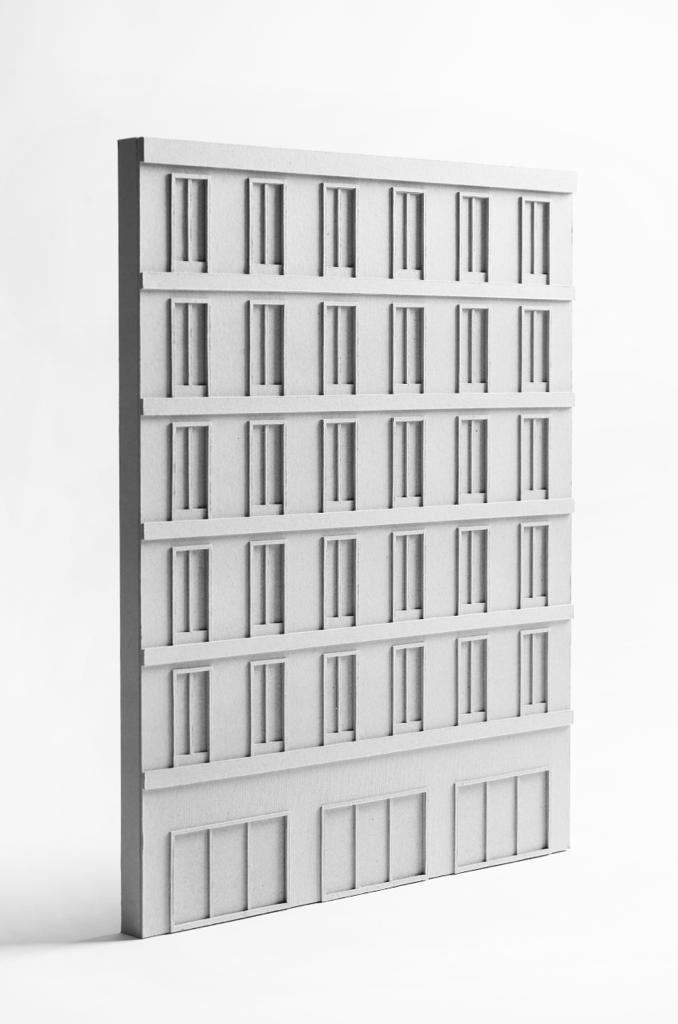
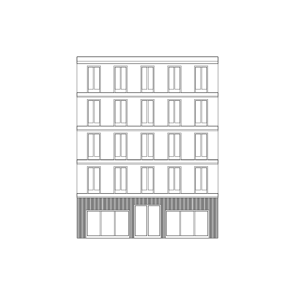
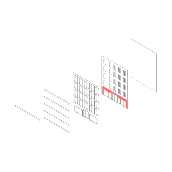
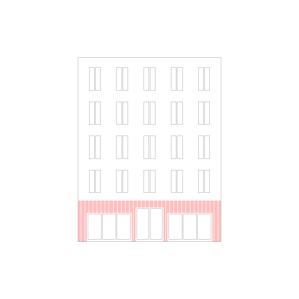
A certain amount of abstraction and discretization is necessary to represent the details of a facade on a model scale. This example guides you through the required steps and exemplifies the description-making process. 2mm cardboard is equal to 10cm on a scale of 1:50. This is a reasonable starting point for the material thickness since many elements like window reveals, ledges, and other features typically present on a facade, fall into the range of the 10cm separation. A layered facade can, in principle, have as many elements as needed, but in practice, it is more common to divide it into the following layers:
Fist layer – this can be a simple piece of card or some MDF, depending on the model’s overall structure. It is not uncommon to have this layer colored or covered with a thin foil to imitate the windows or represent the interior.
Window Layer – this layer has all the cutouts for the windows and doors and sometimes scoring to suggest a particular facade material.
Window Reveal Layer – depending on the design, this includes any raised details that correspond to the windows, doors, and other openings.
First, Second… Ledge Layer – These are optional and show essential elements that characterize the facade. Depending on the model’s design and scale, you may want to extend these layers to show balconies and other features.
As tempting as it might be, it is wise to consider precisely what type of detail needs to be shown in the model. Consider the model as a vehicle to communicate your ideas. In that function, the models converse with you and others. The clearer the model communicates, the better it is for the conversation, and you do not get lost in every tiny detail.